BHUTAN

MIGRATION TO

NEW TECHNOLOGIES

[WIRELESS VOIP]

MISSION REPORT

By

Clif Cox

Clif@eugeneweb.com


For Bhutan Ministry of Communications


Prepared by

International Telecommunication Union


October 30, 2002

$Date: 2003/12/03 00:09:57 $
$Revision: 1.0 $


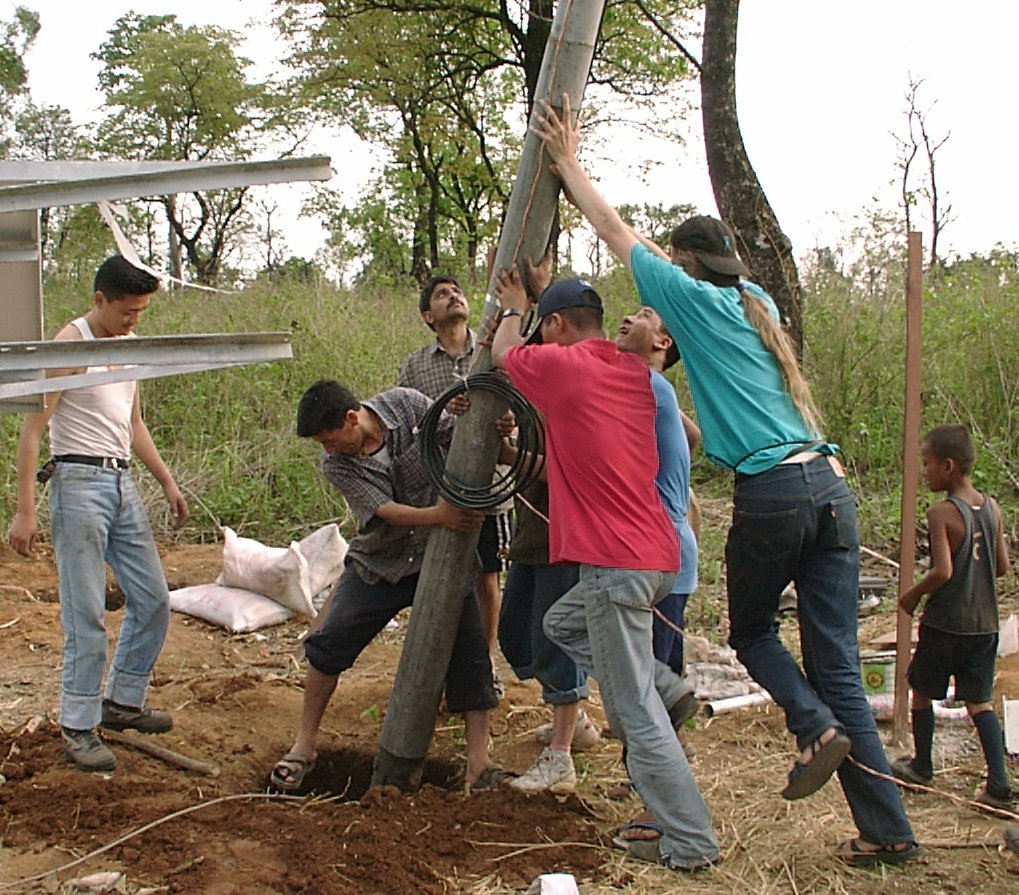
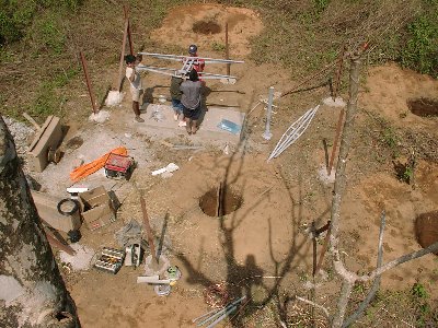
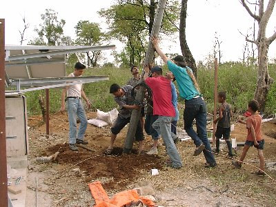
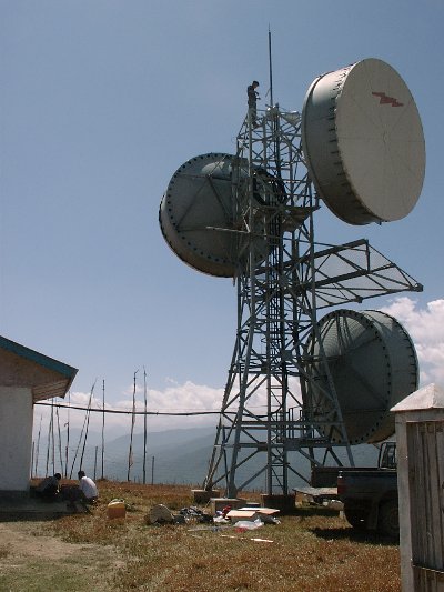
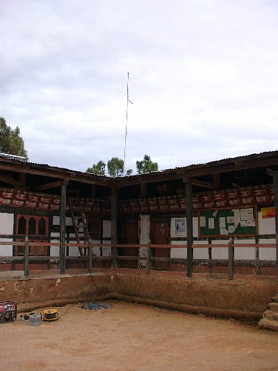
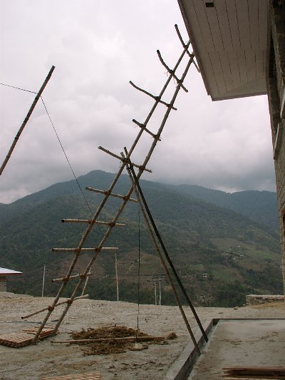
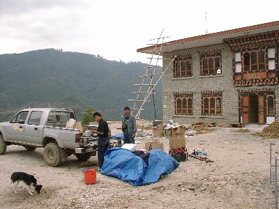
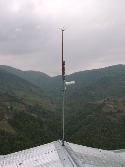
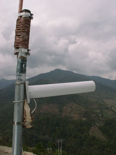
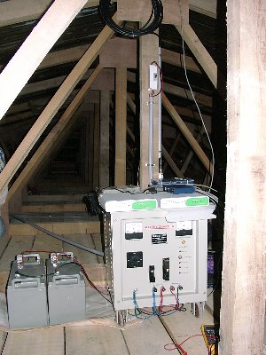
Raising a Repeater in Rural Bhutan
Photo by Tensin Tobgyl


Abstract

A pilot project to use wireless and VoIP technologies to deliver communication services to rural areas in Bhutan, a small Himalayan Kingdom, was completed with encouraging results. Once initial problems with radio interference from other sources were solved the 802.11b radio network became reliable. This allowed the  VoIP equipment to be tuned to accommodate the more variable nature of a wireless network as compared to a wired one. International calls through the PSTN were hampered by a slightly non standard R2 protocol spoken by the local switch. This underscores the importance of adhering to open standards when many subsystems must work together.

Table of Contents

1 Background
1.1 Voice Communications
1.2 Data Communications
1.3 Combining Wireless and VoIP
2 Goals
2.1 Objectives
2.2 Expected outputs
3 Preliminary work
Project Sites
4.1 General guidelines for site layout
4.2 Backbone
4.3 Last mile
4.4 Network layout
Equipment choices and constraints
5.1 Radio
5.1.1 APs/Bridges
5.1.2 Wireless Ethernet converter
5.1.3 Amplifiers
5.1.4 Antennas
5.2 Mounting hardware
5.3 Supplies
5.4 Linux Routers
5.5 VoIP
5.5.1 Billing
5.6 Power
5.6.1 Commercial
5.6.2 Solar
5.6.2.1 Sizing of solar systems
5.6.2.2 Batteries
5.7 Timers
5.8 Weather proof enclosures
Grounding and Lightning Protection
6.1 Further recommendations for lightning protection
Shipping Considerations
Assembly
8.1 Timers
8.2 Repeater boxes
Site preparation
9.1 Installation    
10 Trouble Shooting
10.1 Network
10.1.1 Problems with routing
10.1.2 Bridging vs. Routing
10.2 Radio
10.2.1 Mutual Interference
10.2.2 Radio System Monitoring
11 VoIP equipment installation and configuration
12 R&D
13 Training
13.1 Radio
13.2 Flytech
13.3 Additional training
14 Recommendations
14.1 Radio
14.1.1 Backbone cost trade off study
14.1.2 Repeaters and CPEs
14.1.3 Monitoring
14.2 VoIP
14.3 Billing
14.4 Software
14.4.1 General
14.4.2 Specific features that are important in a wireless system
14.4.3 Specific features that are important in a VoIP system
14.5 Internet access test sites
14.5.1 Solar powered sites
14.6 Lightning protection
14.7 Mounting
14.8 Local construction
14.9 Transport
14.10 Further research
15 Conclusion
15.1 Concluding remarks by local counterpart

A Annexes
A.1 LVD Circuits
A.2 Battery charging and desulfation
A.3 Site Photos
A.4 List of Figures
A.5 List of Tables
A.6 List of Acronyms
R References
R.1 General
R.2 Batteries
R.3 Solar
R.4 Wireless
R.5 Lightning
R.6 Timers
R.7 SBCs
R.8 Other Wireless Projects

1 Background

Good communication services and  universal access are necessary for a higher standard of living and economic growth. However the high cost of legacy PSTN equipment may not be affordable to some developing nations, especially in rural areas which have a much lower subscriber density, or areas with geographic challenges such as large bodies of water, jungles, mountainous terrain etc.

1.1 Voice Communications

There are several paradigm shifts happening in todays telephony markets which are driving costs down by orders of magnitude. First legacy telephony systems are based on Circuit Switched Networks or (CSNs) This means a telephone call is allocated a dedicated circuit from end to end. In the old days this meant a physical pair of wires for the audio to travel over. Today this typically means two 64Kbps channels one in each direction which are dedicated to that call even if no one is talking, and since usually only one person is talking at a time about half of the bandwidth is wasted. For example, a typical small PSTN trunk can carry 24 or 30 simultaneous calls. If the bandwidth were used more effectively the circuit could carry much more if not almost twice as many calls. On the positive side CSN technology is very robust and predictable which made it easier to build reliable telephone networks in the early years of the industry. Because these PSTN switching systems were very big and centralized due to the state of the art at that time, they were very expensive and relatively few were sold to big companies like AT&T. So the market never developed to a point where the prices could drop significantly.

When computer networking technology was developed it was based on Packet Switched Networks (PSNs). Instead of dedicating a circuit of a predetermined bandwidth to two endpoints, packets are sent with little messages inside as each party has something to convey. This utilizes the bandwidth much more effectively. Instead of slicing it up into little pieces that are reserved but not being used half of the time, it is all consolidated in one big pipe that is only used when data actually needs to be sent. As the computer revolution evolved and the Internet grew exponentially so did the market for PSN technology products. This caused prices to fall by orders of magnitude.

Another Paradigm shift that is in progress now is sending audio on a data network rather than sending data on an audio network. Using modems over a Legacy PSTN is an example of the latter. This is a very unfavorable combination  because the modems at both ends usually send a carrier signal even when they have no data to send, and even though the PSTN eventually digitizes the audio it knows nothing about the data encoded by the modem so both 64Kbps channels are constantly in use even though the modems are not sending any packets.

The phone companies saw that this wasn't working very well and that there was a demand for lower cost data circuits, and started providing services like ISDN, Frame relay, and eventually DSL, and ADSL.  These services were designed to let the PSTN handle the communications as data and not audio. But ISDN still used a dedicated 64Kbps or 128Kbps channel so this approach did not capture a large portion of the achievable efficiency. The others had a quality of service metric known as Committed Information Rate or (CIR) which was usually set lower than the maximum bit rate of the Circuit, and paved the way for the consolidation of circuits into one pipe. These were some of the first steps taken in the transition from CSNs to PSNs in Telecom networks.

As high speed wide area networks (WANs) became more affordable and Voice over IP technology developed to become a commercial product thanks to standards organizations like the ITU and IETF, more and more organizations started buying high speed data connections between their offices and providing data and inter-office phone service over these links. Also many Internet Telephony Service Providers (ITSPs) started selling low cost long distance service over the Internet.

One limitation of this technology that may slow down the complete conversion to an audio over data network is that there needs to be power at the subscribers site for the terminal equipment. Legacy telephones are powered only by the PSTN so they will still work if there is  a power failure, and this is often when it's  needed the most. The PSTN is able to provide this by having a battery bank and generator at each switching site. To provide a reliable VoIP system it is usually necessary to have battery backup at each subscriber site.

Telephony equipment manufacturers could no longer ignore the compelling nature of these new communications paradigms, and now no one is building big switches anymore. Most of the new telephony products are based on PC platforms with Compact PCI cards at this time.

1.2 Data Communications

Data rates on wired networks have been increasing by powers of ten over the years, and more recently wireless rates have been catching up. This is due to many factors. Among them are the commercialization of spread spectrum technology, improvements in IC manufacturing processes to fit these radios on  small cards, and the allocation of radio spectrum in the Gigahertz range for licensed and unlicensed use of these devices.

The advantages of wireless networking are hard to ignore and the market for wireless Network Interface Cards (NICs) grew rapidly. Soon they too became commodity items. Initially they were targeted at networks within office buildings and homes, but many users found that they could also be used for long distance communications if the systems were designed properly. This use also became popular and another market grew which provided low cost high quality antennas and amplifiers to increase the range.

This became a low cost alternative to the Microwave links used by the Telecom and broadcast industries, though at not quite the same level of performance. Currently there are products available that work at 11, 45, 100, and 1000 Megabits per second. Though one should note that the expected throughput will be about half of the data rate, and generally the higher the speed the shorter the usable range.

1.3 Combining Wireless and VoIP

Wireless telephony is nothing new, there are microwave links for the trunk lines and Wireless Local Loop (WLL) for the subscriber terminal equipment. But it's mostly CSN based technology and is therefore quite expensive. If one combines a network built out of commodity wireless cards with Voice over IP equipment it is a low cost delivery infrastructure that makes efficient use of the bandwidth it provides. Additionally one gets a high speed data network that can also provide Internet access.


Of course its not quite that easy. Each radio repeater needs battery backup, and as mentioned before so does each subscriber. Also because of the change from the CSN model  to PSN it will be necessary to manage the bandwidth usage so that priority is given to voice traffic and that too many calls are not allowed to be placed simultaneously. This was not an issue with the legacy CSN systems because there were only a finite number of slots on the trunks for calls and when they were out of slots one got an all circuits are busy message.

Overall rapid growth in this area is expected, driven by fierce competition in long distance rates, and the large populations of people currently without good communications services.

2 Goals

2.1 Objectives

2.2 Expected outputs

3 Preliminary work

In the spring of 2001 the Consultant came to Bhutan as a UNV specialist attached to the Department of Information Technology (DIT). The Consultant demonstrated some wireless gear with a usable range of about 8km from a PCMCIA card in a laptop to a repeater and a similar range for some VoIP wireless phones. A proposal for this pilot project was drafted which can be found here [50]. Some more research was done on the equipment list and pricing, and in August the funding for the project came through. The Consultant returned to Bhutan in the spring of 2002 to complete the project.

4 Project Sites

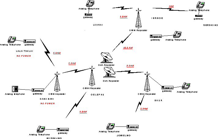
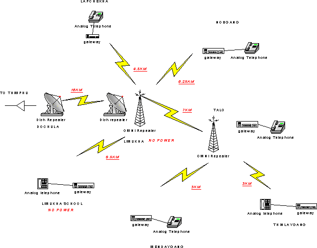
The project has two locations, one in Limukha, and the other in Gelephu serving a total of about 80 customers. The project was intended to test the technology under different conditions. Limukha is more mountainous and Gelephu is flatter but has much more rain and lightning. The Network Operations Center (NOC) for the project was the main switching room of BT in Thimphu. Here were located all the servers, the gatekeeper, and a 30 line gateway which connected the VoIP system to the PSTN. Existing microwave links were used to provide network connections to the remote sites. This was much cheaper than building dedicated backbones, and fortunately spare E1 slots were available running to each area. Here are the site block diagrams:

Limukha Site Diagram
Fig. 1 Limukha Area Diagram.
Source: Tensin Tobgyl, ITU, "Bhutan: Wireless IP based Rural Access Pilot Project" [2.1]

In the Limukha area shown in figure 1 the E1 link ends at Dulchula and the last hop is done over a prototype backbone link which brings the network to Limukha hilltop. Don't be confused by the dish icons in the diagram they really do point at each other. On Limukha hilltop there is also an Omni repeater which serves three Customer Premise Equipment locations (CPEs). Talo Ridge separates Limukha from three other CPEs so we have the Talo omni repeater to cover those.

Gelephu Area Diagram
Fig. 2 Gelephu Area Diagram
Source: Tensin Tobgyl, ITU, "Bhutan: Wireless IP based Rural Access Pilot Project" [2.1]

In The Gelephu area, (figure 2) The E1 link terminates at the PSTN switching room in Downtown Gelephu. The Microwave tower there was used to mount the equipment to cover the surrounding areas. Because the design was very conservative two dishes were used to reach the outlining areas and one omni to reach closer CPEs. Happily it turns out that the omni was able to also reach one of the outlying areas. In each of these three areas there is a repeater to serve the local CPEs.

In this project each CPE  provides either four or eight analog phone lines. The Limukha area has six CPEs serving about 36 customers. The Gelephu area has Eight CPEs serving about 44 customers.

4.1 General guidelines for site layout

The constraints involved designing a high speed data radio system are very similar to ones in a WLL or cellular system. Everything needs to be Line Of Sight (LOS). This actually means a path which is also free of nearby obstructions such as corners of buildings and rooftops, not simply being able to see the other antenna. This is because there is something called the Fresnel zone around the centerline of the LOS path. Objects in this zone are likely to refract some of the signal toward the antenna and cause it to be attenuated. Of course sometimes one can get by with things in the way like a few wispy trees etc. But it's not a good idea and when the leaves get wet they will adsorb even more of the signal.

The range one can get out of each link depends on several things. The most important is probably the chosen frequency band. Because this project focused on a solution using commodity wireless hardware, this meant one of the ISM bands. Namely 2.4GHz or 5.8GHz. The trade off here is the higher frequency allow for higher data rates but shorter ranges, and more rain fade. So more power will be necessary to make up for the loss of signal strength when it rains or snows. At the time of this report 802.11b devices worked in the 2.4GHz band and  provided data rates up to 11Mbps, and 802.11a and others worked in the 5.8GHz band and provided rates up to 50 and 100Mbps. 802.11b equipment was chosen because of the lower cost and higher availability. For a quick introduction to 802.11b please see [20.5].

Once the band has been selected, the other factors influencing range can be adjusted: output power, receiver sensitivity, antenna gain, and data rate. Increasing any of the first three or decreasing the data rate will cause the expected range to increase. It is important  to also allow some margin for rain fade. The Project chose to put amplifiers on the repeaters and slightly higher gain antennas on the CPEs. A conservative rule of thumb for range is to try to limit the distance between repeaters and CPEs to about 8km. It was beyond the scope of this Project to explore the maximum distance between the repeaters but most manufacturers publish sample performance data for different configurations. A conservative estimate would be about 12-15km between 8dBi omnis and about 25-30km between 24dBi dishes using one watt amps. Of course the regulations concerning transmitter power, EIRP, and antenna gain will vary from country to country. There is a good discussion of the US regulations here [20.2].

4.2 Backbone

To build a full network a backbone is needed to deliver the bandwidth to the clusters of customer sites. Ideally the backbone should be much faster than the last mile delivery system so that many sites can be aggregated onto it for transshipment around hither and yon. Also because the backbone is a point to point system, one could take advantage of this and design it to be full duplex. This would more than double it's capacity, and lessen delayed packets due to collisions. This in turn would allow the maximum transit time of packets from one end of the network to the other to be much more predictable which is a consideration for VoIP and other real time data.

In this phase of the project there wasn't enough time or budget to explore a higher speed or full duplex backbone. It's interesting to note that as the number of calls in progress went up so did the collisions and retries. This is very understandable because as was mentioned before a call sends data in both directions and on a half-duplex link this means the two ends have to take turns sending on their shared frequency. Because 802.11b provides so much more bandwidth than is used for a moderate number of simultaneous calls, the collision rate is acceptable and the voice quality should be unaffected. On a system intended to run at near capacity one should seriously consider a full duplex high speed backbone. The most likely candidates seem to be 5.8GHz equipment with amps, perhaps on non-overlapping frequencies using horizontal and vertical polarizations for further isolation.

4.3 Last mile

The last mile delivery is typically structured with one or more repeaters serving the surrounding customers which need LOS or Near LOS (NLOS) to a repeater. In order to account for rain fade and get better range each repeater in the system has a one watt amp to boost the transmit and receive signals. For the repeater antennas 8dBi omnis were chosen. These seemed to be a good balance between gain and a radiation pattern which wasn't too flat. This also provided service to customers who were below the antenna at about a 30 or 40 degree angle. For the Customer sites 13dBi Yagi antennas were used since they were always served by one repeater and it wouldn't have been cost effective to put amps at each customer site. In cases where there is one CPE site way off by itself, it would be preferable to use an existing repeater if possible. In this situation adding an amp to a CPE site would be a viable solution. There are variations on this scheme where the CPE sites all talk to each other using 802.11b "ad hoc" mode and or a meshing protocol, but the available bandwidth typically goes down quite a bit and eventually a repeater will be needed somewhere to get back to the backbone. One should also consider how much bandwidth a community needs when choosing the last mile delivery technology. 802.11a and others can provide upwards of 25Mbps but as mentioned before the range is less. Since there are usually several non-overlapping frequencies available [17], either technology can be scaled up to easily triple the aggregate bandwidth in an area. Most customers who need a telephone line and perhaps an Internet connection can easily be served by 802.11b. Some organizations like hospitals and large government offices might require the higher rates available in the 5.8GHz band and the two delivery systems could compliment each other in these areas.

IEEE 802 Wireless WGs


802.11
802.15
802.16
802.XY
Spectrum
Unlicensed
Unlicensed
Licensed
Unlicensed

Licensed
Freq Bands
2 Ghz
Various depending
on application
10-66 Ghz
2-11 Ghz
450 Mhz - 3Ghz
Range
Local Area
Personal Space
Metropolitan
Area Access
Metropolitan
Area Access
Mobility Support
Portability
Local Roaming
Personal Space
Connector
Avoidance
Fixed
Vehicular Speed
Mobility
Inter-Metro
Roaming
Station Power
Battery
Battery
Mains
Battery
LOS/NLOS
NLOS
NLOS
LOS (10-66 Ghz)
NLOS (2-11 Ghz)
NLOS
Group Charter
PHY and MAC
for LAN
PHY and MAC
for PAN
PHY and MAC
for Fixed Pt.-Mpt.
Wireless Access
PHY and MAC
for Vehicular
Speed Mobile
Access Networks
A quick comparison of existing and proposed 802 wireless standards [18]
Table 1

There is a lot of market pressure to provide a wireless broadband solution as can be seen by the many new proposed standards. See table 1 above for a few, such as 802.16 [19], or 802.XY [18]. Recently the NY Times reported that some entrepreneurs say they have solved the LOS restriction for 80.11b [20]. Most likely future projects will be able to take advantage of these new technologies as the bandwidth needs of rural areas increases.

4.4 Network layout


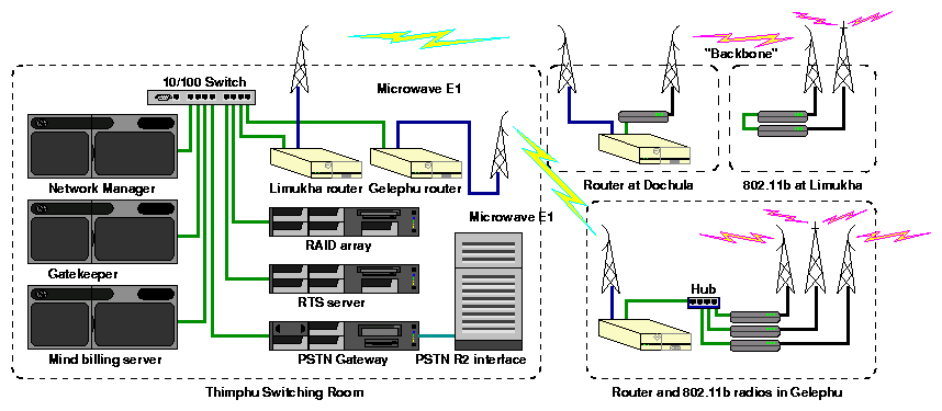
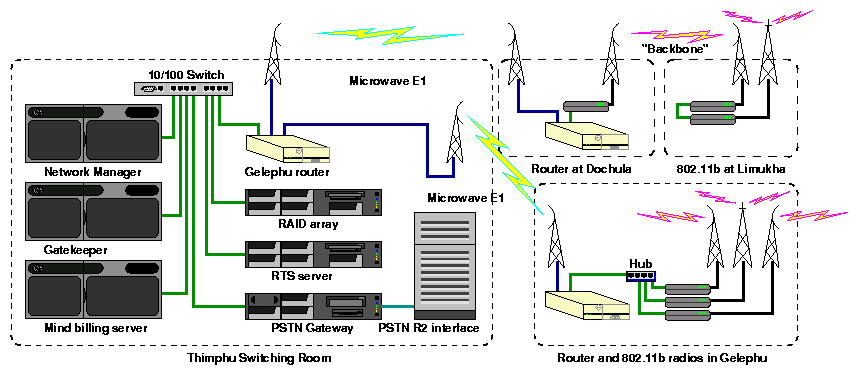
Fig. 3 Original network diagram for the NOC and outward links

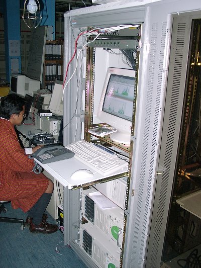
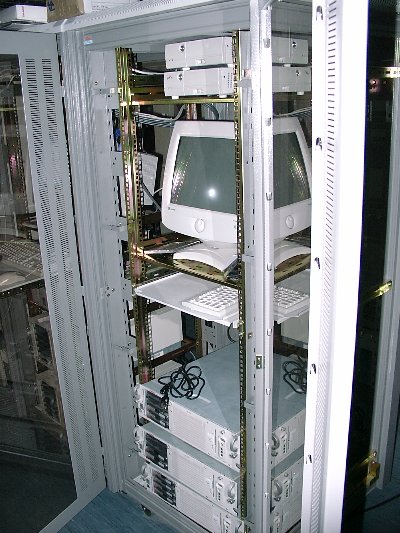
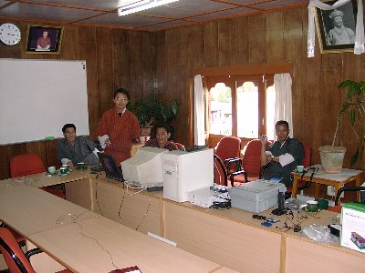
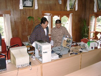
At the NOC in Thimphu were the VocalTec servers, and Flytech routers all on one subnet. Figure 3  shows how it was initially set up, with photos in figure 4. Note that in figures 3, and 18 there is only one tower at each site even though there may be multiple tower icons. The network manager centralizes the management functions of for the VoIP network. The Gatekeeper controls the placing, routing, and logging of calls. The Real Time Server (RTS) logs the calls in real time, also known as Call Data Records (CDRs), and updates customer accounts. The billing server takes the account information and generates statements. The RAID array stores the Data Bases. The PSTN gateway connects via an E1 line to the PSTN using the R2 protocol. An E1 can carry 30 calls at one time so 30 of the approximately 80 customers could call numbers on the PSTN side of things at once. Additionally almost any number of calls to other VoIP phones could be happening simultaneously. Of course statistically only about 10% to 20% of a population will be using their phones at any given time. That is unless you have a high proportion of teenage girls.


a) First rack
b) Second rack
Fig. 4 NOC in the Thimphu switching room

Dochula is the last mountain pass on the way to Limukha, and where the prototype backbone link was tested. Since it was only one hop to Limukha this could be considered a partial test. This was a point to point link configured with it's own SSID, on a different frequency from the Limukha omni, and this allowed it to run with little interference from other segments. At Limukha was the radio for the other end of the backbone and one to serve the Limukha area. They were connected together by a 10BT crossover cable.

Recall in Gelephu there were three radios intended to serve two outlying areas, and a closer one. These were set up as root radios [1] on different frequencies. All had the same SSID though one could force clients onto a particular radio if they were assigned different SSIDs.

These were the main repeaters for the project. There were also secondary repeaters to extend coverage over ridges and into low lying areas. The two project sites each had a large subnet that was further divided down into smaller subnets containing each repeater and the CPEs that they served. This helped organize things a bit.

5 Equipment choices and constraints

5.1 Radio

5.1.1 APs/Bridges
Recall that the 802.11b standard was chosen for the Project's radio gear. Initially the plan was to build the radio networks in each area from products of different 802.11b manufacturers but there didn't seem to be enough time or energy to do the additional research. Also the two top contenders Cisco/Aironet [20.8] and Orinoco/Wavelan [20.9] were very similar in price and performance according to the benchmarks so it was decided to simplify things a bit and just go with what seemed likely to work the best. Each manufacturer seems to have their own terminology for things and what the 802.11 industry calls an Access Point (AP) Cisco/Aironet calls a bridge. Probably because the Cisco equipment also acts as a network bridge. By the way, Orinoco/Wavelan calls their's Outdoor routers. At the time of this project Cisco had two product lines that were considered. The older 340 series which are basically the Aironet products unchanged and the newer 350 series. For the repeaters BR342s were used which have 100mw output, and have come down in price slightly since the 350 series came out. One should note that there is quite a lot of variability in the 802.11b PCMCIA cards on the market. Most are only 30mw output as are the 340 series cards. However the Cisco 350 series PCMCIA cards are one of the few with 100mw output so a few of these were purchased for experimenting with and site surveys. Recently 200mw cards have also became available.

If one looks at the 802.11 products closely they will notice that most of them either are just a PCMCIA card, are an adapter from a PCMCIA card to another form factor, or are a single board computer with one or two PCMCIA cards in it. Recently a few other form factors have come to the market namely Compact Flash (CF) and Mini PCI (PCI). From this it's clear that the radio components are always packaged in a popular small card standard and additional functionality is built around it. When comparing the price/performance of different products it's good to keep in mind the hardware/software costs. For example 802.11 PCMCIA cards vary from $50 to $100 or so, and Single Board Computers (SBCs) can be mass produced for $150 plus or minus. So a low end AP should cost about $200 and they do. But compare that to a high end unit like the Cisco BR342 or Orinoco Outdoor router and one wonders why the cost is on the order of $1000, many times higher. The answer is software and the companies good name. Orinoco makes this obvious by having several products that use the same hardware platform which can accept one or two of their wireless cards and are distinguished by the price / feature set of different firmware versions.

A more cost effective and flexible solution would be to take advantage of the new SBCs that are coming out on the market like the Soekris [42], and Musenki [41] SBCs. Populated with the wireless cards of one's choice they can be configured for virtually any situation. When a new wireless card becomes available just download the drivers and try it. One is not locked into a particular frequency band, data rate or vendor. There is a broad spectrum of free software available for these boards, with contributions from many people all over the world. One is not limited to the feature set offered by just one company.

Additionally this supports a philosophy of using a small number of modules to be used in different configurations depending on what's needed at each site. This way the inventory of different spare parts can be reduced. For example PCMCIA cards can be used for repeaters, CPEs, or laptops. SBCs can be used for repeaters, CPEs, VoIP gateways, or wired E1 routers. All using very similar software.
5.1.2 Wireless Ethernet converter
Because the VocalTec equipment was not wireless, each CPE also needed a wireless client adapter. Commonly these are PCMCIA cards but a stand alone device was called for here. The Avaya Wireless Ethernet Converter (EC) [20.3] was used and worked well for this pilot project, though it had some shortcomings. Originally all CPE sites were to have just one GW each. However for various reasons a couple of sites got rearranged or consolidated so that there were two GWs at these sites. The Avaya ECs could only handle just one network device on the wired side so this new arrangement didn't work. Apparently there is a Linksys product that will do full bridging [20.4],  but is not clear weather the AP also has to be a Linksys or not.

The other missing features for these products are that there is seems to be no way to monitor signal strength or to use SNMP with them.
5.1.3 Amplifiers
Because 802.11 is simplex system, ie. the radios transmit and receive with the same antenna on the same frequency,  when using amplifiers they need to be bidirectional. These will amplify the receive signal as well as the transmit, but they cost quite a bit more than unidirectional amplifiers which can be used on full duplex links. There are several vendors of bidirectional amps, Hyperlink [20.6]and YDI [20.7] are two popular companies and their amplifiers seem to be similar in price / performance though the Consultant doesn't have much experience with YDI. Hyperlink also sells antenna kits with their amps which are competitively priced. The 802.11 repeaters used the Hyperlink 2.4GHz one watt amps.

Full duplex links typically use separate transmitters and receivers each with their own antenna. If a full duplex link were to use amps then then a transmitter  would use one to amplify the transmitted signal, and a receiver would use a different type of amp to amplify the received signal. These amplifiers are cheaper to build because they only amplify in one direction.
5.1.4 Antennas
Antennas vary in price quite a bit, and one can even build their own without too much trouble. Hyperlink has a good selection of moderately priced antennas, and will give one a discount if they order a kit. The Omnis and Yagis are about $100 and the dishes have come down a bit to about $70. Most of the 802.11 antennas on the market are readily available with weather proof plastic enclosures (radomes ) except it seems, the dishes. This makes it rather expensive to design backbone links where there is snow and ice. For CPE antennas next time the Consultant would recommend Yagis from this South African company [5.1]they seem very solid and weather proof and are only $28[5.2].

5.2 Mounting hardware

It's helpful if all the mounting hardware uses readily available nuts and washers because one will lose more than one cares to admit by dropping them off of towers or roof tops. Also u-bolts can be easily made from long pieces of threaded rod sometimes called all-thread. It's good to keep a supply of several sizes handy along with a box or two of nuts and washers. Also it can be used for mounting to concrete footings.


a) Cracking when bolt is tightened
b) Hard to find proper sizes in the field
Fig. 5 Problems with expansion bolts

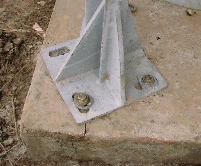
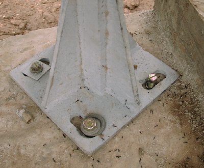
Figure 5  shows some examples of the problems one can encounter fastening to concrete footings. The intention of course is to pore the concrete with the bolts in place so the installing crew can come along later and bolt down the equipment mounts. Usually this requires too much coordination between the two crews so the concrete is pored without bolts. Then the installing crew comes later and drills the holes. So far expansion bolts have been used but as one can see in figure 5 that there can be problems with the concrete cracking when the collar expands, or just finding the correct sizes of bolts, expansion collars, and washers can be tough when supplies are running low. The Consultant recommends using all-thread and epoxy anchoring compound [5.6]. This way the same supplies of all-thread, nuts and washers can be used for anchors as well as u-bolts.

5.3 Supplies

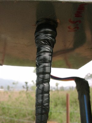
It's important to waterproof cable connections properly. One way is with special rubber tape that self seals to itself once applied. It's very important to cover the rubber tape with a UV and weather resistant electrical tape because the rubber tapes will eventually crack and breakdown with prolonged exposure to sunlight. See figure 6 for examples.


a) Example of coax entering box
b) Electrical tape being applied over rubber tape
Fig. 6 Proper taping of connections
c) Example of taped Amp connections

One can also use a brush applied waterproofing compound such as ScotchKote [5.7].

Another handy item is epoxy putty for sealing holes in roofs and the like. The common brand name in Bhutan is M-seal. Of course wire ties are a good way to dress cables but don't use them on lightning ground wires because they will melt. It's better to use stainless steel straps instead.

5.4 Linux Routers

The thought here was to demonstrate the viability of open systems and especially open source software solutions as alternatives to more expensive commercial products. Briefly, the Consultant put together very small computers with E1 cards running Linux which served as routers at the ends of the microwave E1 links. For more details on their configuration and maintenance please see the Flytech training manual [2].

The Flytech boxes did meet most of these expectations. They excelled at being flexible and provided a work around for an apparent problem with the Cisco Bridges. Also they were much more capable than a mere router needed to be, which was a double edged sword. On one hand it allowed network monitoring and logging to be done from one box (See section 10.2.2), on the other hand the system image was quite large and this made it a bit awkward to back them up. Because they were essentially small PCs they suffered from some of the same limitations, such as a risk of file system corruption when there was a power failure, and the possibility of hard drive failure. Because they are so flexible they may require a little more skill to administer if one is contemplating adding features. Though for the usual additions to the network, typically only one file needs to be edited.

If one agrees that this is a good direction to go and that the flexibility gained was a factor in the success of this project then most of these issues can be addressed. The possibility of file system corruption can be almost completely eliminated by using a journaling file system. The Consultant has done this on other Flytechs and no longer has to worry about power interruptions. The Hard drive can be replaced with a compact flash card since the Flytech's have a CF slot. The tradeoff here is that there is limited space for additional applications and no space for logging large amounts of data. On the positive side back up is a breeze, and administration tends to be simpler because the system is smaller and more focused on one task. For sites with battery power there is also a DC supply option for the Flytechs.

All in all the Flytechs did their job well, but they were probably overkill. The cost for a Flytech was about $2000 total, comparable to a Cisco router which is much less capable. Though if the system monitoring is to be done from another server then the routers could be scaled down somewhat with a similar reduction in cost. The Soekris SBCs might be able to replace the Flytechs someday when an E1 card is available for their Mini PCI slot. Soekris has plans to come out with such a card but the timing isn't certain. This configuration might cost around $500 to $1000 USD but that's just a guess.

5.5 VoIP

For the VoIP component of the system there are a lot of considerations but due to time constraints the Consultant feels that some were left unaddressed. Still a reasonable choice was made that worked adequately. Initially there was interest in wireless VoIP products, and at the time of the research there were only one or two on the market. Primarily the search was for a fixed wireless VoIP residential gateway rather than mobile wireless VoIP phone. E-tel provides the former in their GW210 model [4], and Symbol's NetVision phone [5] is an example of the latter.

The Etel GW210,  even though it was only a two port unit, was felt to be cost effective because it combined the VoIP and wireless components of a CPE into one unit. However it was difficult to confirm that it would interoperate with any of the gatekeepers (GK) that the project was looking at. In hindsight E-tel's list of GKs that were compatible with the GW210 could also have been checked into and then billing systems that worked with those could have been found.

 Eventually VocalTec [3] was chosen as the supplier of the VoIP equipment for several reasons. A complete solution with a billing system was needed. They were very helpful, and in fact they were one of the few vendors that returned phone calls. Also the project had the usual time constraints and they seemed to be the only choice when it was time to make one. VocalTec was unable to interoperate with third party gateways (GWs) so other products could no longer be considered, but this also had it's advantages because the two viable models had four and eight ports, compared to most (but not all) of the others that had been looked at which were one or two port units. This allowed the CPEs to be consolidated so they served a small cluster of buildings with one antenna. This is preferable to many CPEs and antennas because there is less contention for the radio channel.
5.5.1 Billing
VocalTec recommended the Mind billing system, a third party product which seems to be working well. Again if there had been more time there was already an in house billing system in use by the ISP branch of Bhutan Telecom (BT) and it might have been possible to adapt that one to the VoIP project. Especially since there were local programmers who maintained it.

5.6 Power

As noted above, one of the other differences between a legacy telephone system and a VoIP system is that the CPE must be powered locally at the Customers site. This is because there are no wires to carry the power. Now if one were considering a wired VoIP system using 10/100BT then they could take advantage of a new development called Power over Ethernet (PoE) which runs power over the Cat 5 Ethernet cable. In this case though the power had to be provided locally, so instead of a centralized and easily manageable bank of batteries at the Switching center one needs batteries at each customer site along with a charger and Low Voltage Disconnect (LVD).
5.6.1 Commercial
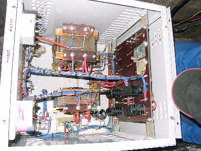
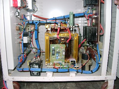
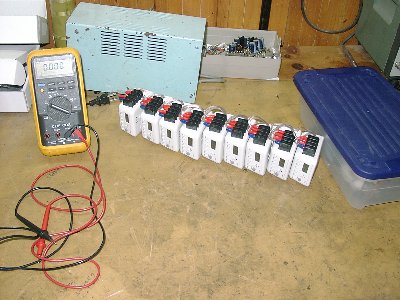
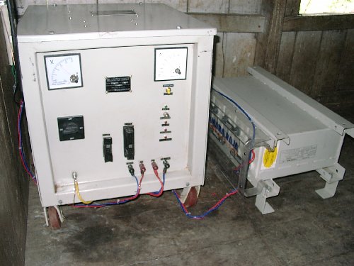
At sites that had commercial power a battery charger that had a built in LVD was used . Apparently there weren't a lot of choices locally  for this product and the one that was available was not a great match for this application. The unit was larger and heavier than it had to be (figure 7).


Fig. 7 The commercial charger was a bit larger than it needed to be

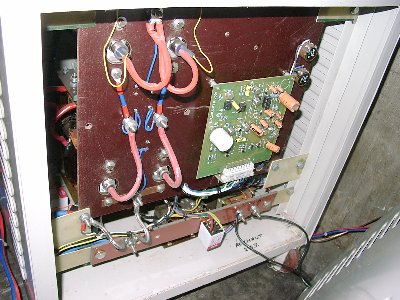
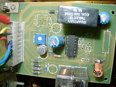
Also it seemed impossible to get documentation for it, and it appeared to be malfunctioning. Eventually an unlabeled LVD adjustment was discovered (Fig 8 d) and, that it was not set properly at the factory. In fact they seemed to be set randomly on each unit. So trips had to be made back out to the CPE sites and readjust the LVD set points. This was after a couple of batteries were damaged.


a) Top of Charger
b) Back of Charger


c) Right side of Charger
d) Closeup of LVD board showing adjustment
Fig. 8 Inside the commercial charger

The lesson here is carefully research the products for one's system. Even though it is better to buy locally it still may not be the wisest thing to do.
5.6.2 Solar
For sites where commercial power was unavailable solar panels and charge controllers were used. There were both repeater and CPE sites which used solar power. The panels were purchased from Tata BP solar and were 70 watts each.

The Consultant recommended charge controllers with integrated LVDs, and suggested several such solar chargers during the selection process [14]. But apparently there was a lot of pressure to get the project underway and not enough time to evaluate them all. An outside vendor recommended the Trace C35 and C40 thinking that they also had LVD options, This is an understandable mistake because they can indeed be used as an LVD but not when they are configured as solar charge controllers. Also the specifications can sometimes be ambiguous, when in doubt it's best to contact the manufacturer. This was still an excellent choice because trace produces some of the highest quality alternative energy products on the market. Eventually a standalone LVD was found to work with the C35 but it's quality was suspect.

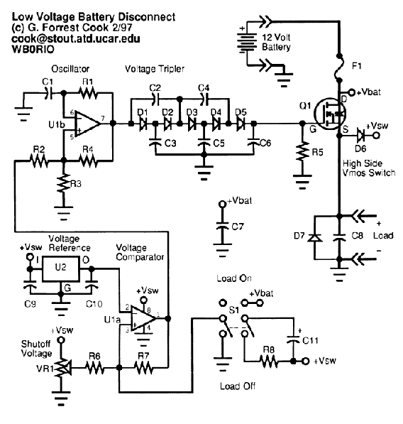
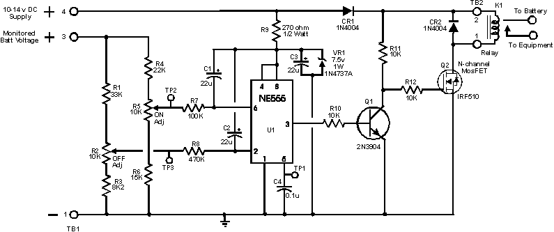
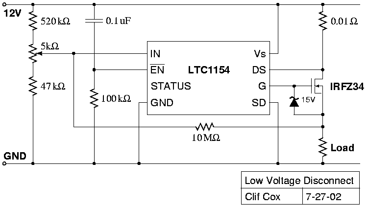
As these examples show it can sometimes be difficult to find units correctly sized for a site with all the desired features. In this case building one's system out of several smaller units which better fit the constraints is probably advisable. In this instance the high cost of quality LVDs [15], or the low quality of locally produced units seemed to be an issue. The Consultant eventually did further research and designed a very low cost (VLC) LVD which could be used for any repeater or CPE site. The parts cost is around 10 to 15  USD. See Appendix A.1 for details.

There were several solar powered CPE sites which required much less power than the repeaters, and it seems there are quite a few small charge controllers with LVDs available. Though the Specifications are not completely clear on this matter the Trace C12 seems to be LVD capable when it is configured as a charge controller unlike the C35 and C40. In any case the reliability of future CPE sites would benefit by having integrated Charge controllers, and LVDs.

Also note that when the sun is shining that no part of a solar panel should be shaded. This is because a great number of cells in a panel are connected in series, and that when shaded, a cell will act like a resistor. This will greatly reduce the output of a panel even if only a corner is shaded.
5.6.2.1 Sizing of solar systems
The solar repeater sites were sized such that they could operate from batteries for eight cloudy days in a row and be recharged in three. During cloudy days the panels will only put out about 10% of normal but to be conservative it is assumed to be zero. To calculate the size of the solar array and battery bank it helps to make some approximations. First the output of the solar panels need to be averaged or "derated" over a whole day because they will only give their rated output during high noon and if they are not too hot. In fact many solar manufacturers rate their panels at 25 Degrees C but they are usually much warmer and so put out less power. Also it is convenient to talk in terms of amps and amp hours even though batteries change voltage with their State Of Charge (SOC) and the number of watts per amp hour will actually vary.

For the calculations one starts with the power draw of the load, for the repeaters that was usually 18 Watts.  Then one needs to estimate how many hours of direct sun light the panels will  usually get on a sunny day for a given site. Six were used here, please see table 2 for example calculations.

1)
First note the size and deratings of the panels and batteries.

Panel wattage = 70W
Panel volts = 17V
Derating = 95%
Battery Ah = 100
Maximum usable = 80%
Charging efficiency = 75%
2)
Next get the average current draw for the load,

Current = Load Watts / Volts
= 18W / 12V = 1.5A
3)
Then calculate how many amp hours the load consumes in a day.

Total load per day = 24 hours * Load Amps
= 24 hours * 1.5A = 36Ah/day
4)
Also during the eight day autonomy period. This gives the needed battery bank capacity.

Days autonomy * Amp hours/day = Total amp hours for autonomy period.
= 8 days * 36Ah/day = 288Ah
5)
Next one needs to realize that the batteries can't be discharged completely
because it will cut their expected lifetime almost in half.

Amp hours of autonomy / Percent usable = Battery bank size.
= 288Ah / 0.80 = 360Ah
6)
Then the fact that one will always put more back into a battery than
one can get out of it needs to be accounted for. This is the expected
charging efficiency (or inefficiency).

Amp hours of autonomy / Charging efficiency = Amp hours to put back

So about 384 Amp hours needs to be put back into the battery bank
after a full eight days of cloudy weather.
= 288Ah /  0.75 = 384Ah
7)
Now find out how many amps are needed during the sunny part of the day.

Total recharge Ah / Days for recharge / Hours of sun per day = Total Amps during sun
= 384Ah / 3 days / 6/day = 21.3A
8)
Next find out how many amps the load will need during the
sunny part of the day to break even with the battery drain at night.

Load Ah per day / Hours of sun per day / Charging efficiency = Load sun amps.

Note this is a short cut that made it seem a little worse than it
was because during the sunny part of the day the load is powered directly
off the panels and the battery inefficiency doesn't come into play,
but the result wouldn't change very much and it is better to
overestimate ones power usage a bit.
= 36Ah / 6 Hours / 0.75 = 8A
9)
Now add the current needed to recharge the batteries with  what's
needed to power the load at night which will yield the total current
required in sunny weather.

Recharging current during sun + Load current during sun = Total current needed during sun
= 21.3A + 8A = 29.3A
10)
Then get the average amps each panel can be expected to produce.

Panel Derating * Watts / Volts
= 0.95 * 70W / 17V = 3.91A
11)
Now one can easily calculate the number of panels needed.

Total amps / Amps per panel  = Rounds up to number of panels.
= 29.3A / 3.91A/ Panel = 8 Panels
12)
Last but not least do the same for the battery bank.

Battery bank size / Each battery  =  Rounds up to number of Batteries.
=  360Ah / 100Ah/Battery = 4 Batteries
Calculations for solar system size
Table 2


In some situations one could save some money by installing a Maximum Power Point Tracker (MPPT) which allows the panels to supply current at their most effective operating voltage rather than whatever voltage the batteries happen to be at. There are claims that these devices can get an additional 25% to 30% out of the panels but this is often not realizable. Still in certain cases they are warranted [13]. If one used an MPPT as a charge controller then the above calculations would be more accurate if they were converted to use Watts and Watt hours instead of Amps and Amp hours. One can get a hint of the difference this might make if the solar panel wattage is divided by the nominal battery voltage (12V) instead of the solar panel working voltage (17V) in step 10 above.

One MPPT on the market that seems to be sized right for the CPEs is the B.Z. products MPPT200 [13.1]. It should be seriously looked into as an alternative to the Trace C12 since it also has a built in LVD and is competitively priced.
5.6.2.2 Batteries
Lead acid batteries still appear to be the most cost effective solution for most situations though one should take into account the cost of an environmentally sound way of disposing of worn out batteries when making comparisons. Again in legacy Telecom systems all the batteries are at the local switching center where they are kept in a controlled environment and monitored regularly. This makes it feasible to use ordinary flooded cell lead acid batteries with Catalytic recombiners. On the other hand a VoIP system requires many batteries in the field where there is little control over operating conditions. Also they often need to be transported and handled by less experienced people. In this situation sealed lead acid batteries are the better choice even though they are more expensive. There are several types of sealed lead acid batteries, Valve Regulated (VRLA), and Gel-Cells are two examples. Gel-Cells won't spill if tipped over and can often be mounted in any position. Proper venting is also important, especially for flooded cell lead acid batteries. There have been accounts of roofs being blown off by hydrogen explosions.

In any case there will be a sizable investment in batteries for the system. Therefore one would want to maximize the lifetime of the batteries and minimize their maintenance requirements In order to lower the cost of ownership. This means extra care should be taken when choosing a charging / monitoring system. Again all things being equal it is desirable to buy locally but carefully research the quality of all products before making a choice.

There is a wide spectrum of chargers available for lead acid batteries. Generally the higher end three stage chargers are required here, and ideally one with an integrated LVD. The LVD protects the battery(s) from being over discharged which would seriously damage them. In fact if a Lead Acid battery is only discharged to 80% of it's capacity then that will almost double its lifetime [9].

Also it's interesting to note that it gets harder and harder to put energy back into a battery as it gets fuller and fuller. This is called it's charging efficiency, and it varies nonlinearly with the battery's state of charge (SOC) [11]. The Consultant's hypothesis is as the battery is charged the chemical reactants are converted to the charged state. As the battery nears full charge less and less reactants are available for conversion, and the internal resistance of the battery goes up. In the end about half of the power going into charging the battery is wasted as heat. If this is not taken into account when designing solar systems the panels may be under sized and may not be able to keep the battery bank fully charged. Most likely  this is not an issue here because of the aggressive recharging time that was required for these solar systems. There are several good papers on the appropriate design of battery systems for solar sites at Sandia Labs [10].

5.7 Timers

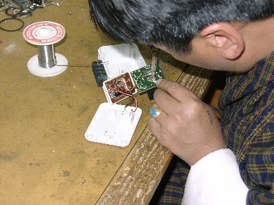
As a bit of added insurance for the repeaters the Consultant felt that it wouldn't hurt to add a timer that would power cycle the unit once each day at four in the morning. Sometimes computer based devices (also known as embedded systems) can lock up for unknown reasons and then need to be rebooted. A timer is a low cost solution that can save one a trip into the field. If one had more control over the specification of the embedded systems then a watch dog timer is the preferable way to protect against these type of problems. Watch dog timers are built into a lot of modern microcontrollers. They act like a dead man switch and once activated they need to be "touched" by the software every half second or so or they cause the system to reboot. If properly implemented they add a good fail safe component to one's embedded system. For this project low cost digital timers were purchased from Amazon.com [34] and modified to work on 12V. There are also ready made 12V digital timers but they seem to be quite a bit more expensive, probably because there is not as much demand [35].

5.8 Weather proof enclosures

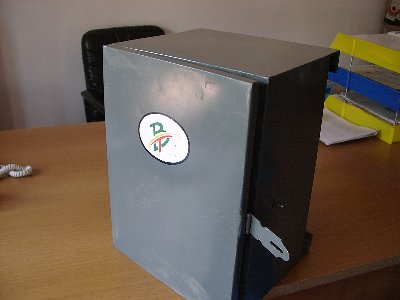
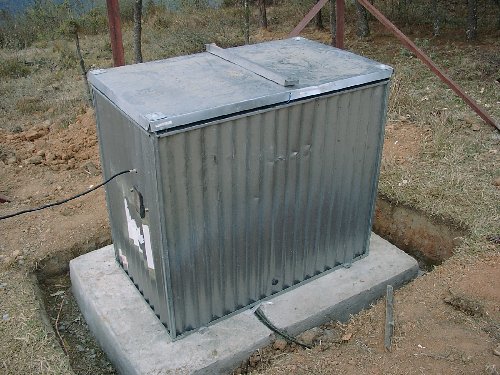
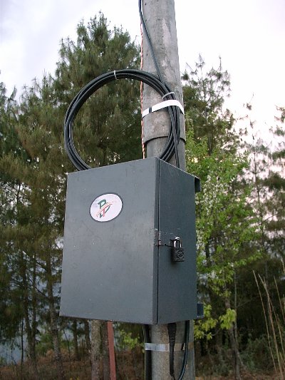
The repeater equipment needed to be protected from the elements and rather than shipping metal boxes from some faraway country a local supplier was sought for them. It turned out that one of BTs metal shops was able to make very nice weather tight boxes for about $20 each, compared to $40 from India, and $100 from the US. They even sported sharp hand painted logos!


a) Weather tight box made in Bhutan
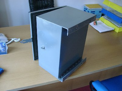
b) Slight problem with mounting
Fig. 9 Weather tight box

There were a few issues with mounting though because the Angle iron was upside down. See figure 9 b above. Certainly the next batch will come out just fine.

6 Grounding and Lightning Protection

There was a lot of concern over proper grounding and lightning protection, and for good reason. In Gelephu There are lightning storms several times a week in the summer. Sometimes At night it's as if someone were arc welding in the sky, and one can almost use that light to see by!

The Bhutanese have a lot of experience with lightning protection because after all they live in the land of the thunder dragon. Generally they use lightning rods with spikes and heavy metal straps on the roofs running to deep earthing pits. These pits are usually about 3 meters deep with a plate of copper in the bottom to which the grounding strap or wire is bolted. The pit is filled with layers of salt and charcoal both of which are conductive and help to retain moisture. The top meter or so is filled back in with dirt. In very dry areas an additional measure which helps is to leave a pipe in the ground which ends near the top layer of  salt and charcoal. A funnel can then be used to poor salt water back into the earthing pit [27]. This will keep the ground moist and replenish the salt content which dissipates over time. There are also other chemicals that will increase the conductivity of ones ground and last longer than salt [28].

At sites where only an equipment ground was needed copper stakes were used connected together by the grounding wire which then ran to the equipment. A earthing meter was used to measure the resulting ground to check if adequate.

Even so with all this experience and good practices there are still many thousands of dollars damage caused by lightning each year. For the project's relatively small sites there was some discussion as to what the most cost effective earthing practice would be.

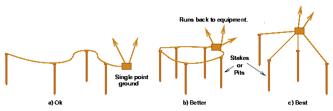
What it boiled down to was that large voltage potential differences are to be avoided. Keep in mind the with even the best grounds the area surrounding a lightning strike will rise tens of thousands of volts for a few micro seconds. This includes all of ones equipment if lightning strikes the tower, it just can't be helped. But by itself a rise in potential doesn't cause damage. It's only if part of ones equipment is swinging to the tune of a different voltage that causes problems [23]. Single point grounds are the best way to prevent this from happening. This will also avoid ground loops which are always undesirable in electrical systems. Simply put, a single point ground is where each ground stake and each piece of equipment including the lightning rod have separate runs of grounding wire to a common point, usually a terminal strip or bus bar. If that sounds too expensive there are some shortcuts one can take that don't appreciably diminish the protection provided.
See figure 10.

Fig. 10 Different grounding examples

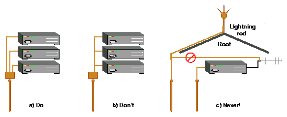
One should avoid at all costs inadvertently grounding different interconnected parts of a system to different grounding points. If there is a nearby lightning strike then most likely the different grounding points will develop high potential differences as the surge passes through them, and this will destroy the equipment. This is an example of how an improperly grounded site can actually cause the equipment to be damaged instead of protecting it. See figure 11 c.


Fig. 11 Equipment grounding examples

It's the Consultants opinion that there is a situation where two grounds are acceptable, as long as there is no electrical path from one one ground system to the other. Thus keeping them separate so that even though they may be at different voltage potentials no current flows between them. Since lightning is so unpredictable guaranteeing that no current will flow is difficult. It would probably be unwise to have two separate grounds in the same building because the strike could jump from one system to the other. On the other hand it might be best to give two towers 50 or more meters apart separate grounds. In this case one would use separate grounds and carefully ground cables that came in from outside the local grounding system of each tower. Commercial power is a good example of cables entering from the outside. It's common to put large Metal Oxide Varistors (MOVs) across terminals in the panel to protect against surges and some strikes.

For example there may be a microwave tower at a site but there are other antennas on it using the same band as the equipment. Then it may not be feasible to put one's radios on the same tower. If one erects a smaller pole or tower a hundred meters away then it may not be practical to ground the two towers together.

When grounding ones antenna or coax it is a good idea to have several loops of coax before it enters the equipment box or building. Because lightning causes such rapid surges even small inductances have very high impedances. This means lightning will tend to avoid going through coils and try to find a short straight path to earth.

For the repeater sites that were not colocated on preexisting towers, lightning rods were installed at the top of the poles with the antenna about a meter below. Additionally it's advisable to run the grounding wire for the lightning rod down the opposite side of the pole from the coax giving it the best chance to survive a strike.

providing single point grounds for solar repeater sites was easy. Sites with commercial power were harder because the power line was also grounded somewhere else. The neutral side of the power line isn't such a problem because it could go though ones local single point ground but the hot side could transmit any surge into the site. In the US the model for lightning induced surges on the power lines is a nanosecond rise time up to 6000 volts with a 20 microsecond decay.  It would be best to use a lightning arrestor or surge suppressor on these lines when they enter the electrical "panel" for a site.

Often lightning arrestors are of the gas discharge type, and these fire relatively slowly when compared to the rise time of a lightning strike which is on the order of nano seconds.  TransZorbs are another common surge suppressor based on controlled avalanche diodes with sub nano second response times [31].  These are often useful in protecting equipment on phone lines from surges caused by nearby lightning strikes which are then inductively coupled into the lines. ONEAC is another manufacturer of high quality power conditioning equipment and surge suppressors [32]. They also have a popular phone line suppressor [33].

For most of the CPE sites lightning rods were not required because the metal roofs acted as a shield. The Yagi antennas were installed just under the eves pointing out toward the local repeater. It would be extremely unlikely that lightning would curl under the roof to find the antenna. Most of these roofs didn't have lightning protection being village houses, but sometimes there were cables holding the roofs on that would also conduct a lightning strike to ground. This is another example of a separated lightning and equipment grounding system.


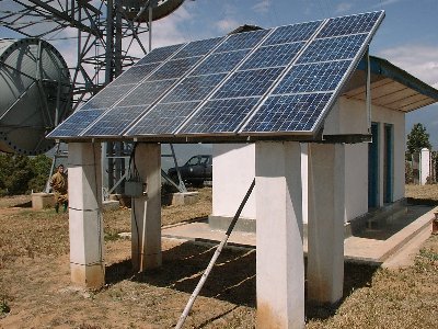
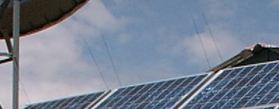
a) Solar Panel at Limukha with static dissipating points

b) Closeup of top of panel
Fig. 12


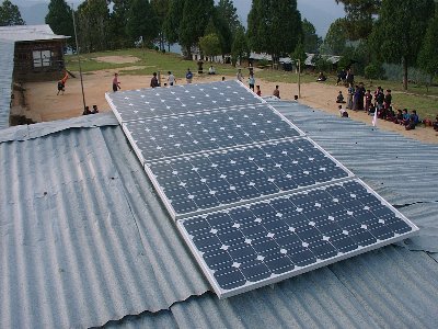
Last but not least preventing strikes in the first place should probably get the most attention. A lot of sharp spikes mounted on a tower will tend to pass the charge on the tower into the air and either neutralize the difference in potential or pass a lot of it off to the surroundings so the tower dose not stand out so much as a likely target. One product that does this is Stati-Cat [25]. Something like the Cortana Static Kitty should work great on the repeater poles. Also note that it's advisable to put something like this along the top edge of solar panels so that they are not a target. This was done at the solar powered microwave stations such as the one at Limukha (figure 12), and the sharp spikes on the lightning rods also serve this function to some extent. Of course one could build these locally and probably do a good job with some attention to detail. Stainless steel is the best metal for the spikes. Don't use steel it will be useless after it rusts. Brass or bronze are also good second choices [24].

6.1 Further recommendations for lightning protection

One practice that the Consultant wasn't too keen on was to take fairly heavy gauge wire and unwind the strands into two pieces thus giving twice as much wire for grounding. It seems that with all the expense to dig the pits and buy the copper rod grounding kits and such, that to cut costs on the actual grounding wire is not a good balance of resources. This smaller wire becomes one of the weakest links to ground, the very thing one is trying to improve. There are accounts of 1/2 inch copper pipes utterly evaporated and puddled. Others recommend double-O size wire to safely handle the current of a strike.

Even though crimping is an acceptable way of connecting wires and stakes it is still prone to corrosion and other problems. Especially if one uses dissimilar metals which should be avoided for this reason. A step up from crimping is the irreversible compression-type bond. The same metal is used for both the wire and the compression fitting, and the crimping pressure is high enough that the two are "welded" together. This type is UL467 [33.4] approved for underground burial. Burndy has a line of these connectors, please see the following references for details: [33.1], [33.2], [33.3]. Clamps are probably less reliable than crimps.  Solder can't be used because it melts away at the first trickle. Unless done correctly braze welds may not create a proper bond. A another reliable method that may be warranted sometimes is exothermic bonding [26]. This actually welds the wire and stakes together with a surface area that is greater than the cross section of the wire. Cadweld® is a well known exothermic bonding product [30]. There is also a manufacturer of a exothermic bonding product in Bangkok [29].

Try to find better surge protection for the phone lines where they connect to the residential gateways. Possibly the TransZorbs [31], or the  ONEAC OnLine product [33] will work.

Ethernet cables that run from the inside of a building to a tower need to be treated as two cables connected and grounded at the point of entry to the building. Often these are Unshielded Twisted pair (UTP) and require a special grounding kit. This supports the single point ground practice and ensures that the the power and data cables will swing in potential together at the end where the data radio (repeater) is.

7 Shipping Considerations

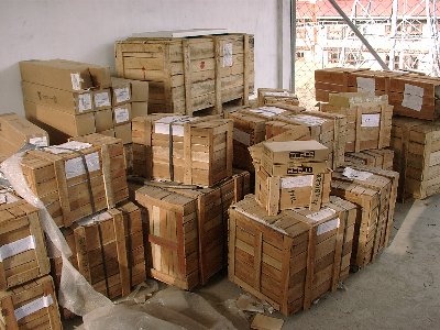
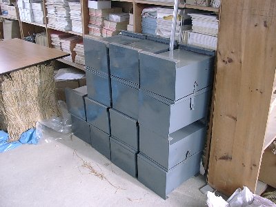
A little more care is required when planing how items will be shipped in developing nations. There were a lot of problems with the DHL shipments, and the VocalTec shipment came in on a truck from Phuntsholing with very little protection from the elements. Though the crated shipment from India seemed fine (figure 13 a) and of course the repeater boxes which were made in Bhutan are pretty indestructible (figure 13 b).


a) Chargers, Batteries, and hardware from India
b) Repeater Boxes made in Bhutan
Fig. 13 Example shipments

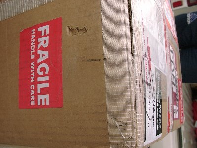
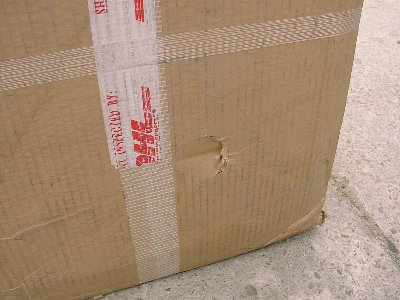
There were a lot of logistical issues involved shipping hardware from the US. First and foremost it's very costly to ship hundreds of kilos worth of equipment halfway around the word. Then there is something called volumetric weight charges which means a box will be charged not only according to it's actual weight but also to it's size. If one merely ordered components from many vendors and had them shipped to them it would cost much more than if first they were consolidated into larger boxes. So that is what was done here. This means that most of the original packaging had to be thrown away and each item had to be repacked carefully in the larger boxes with just enough cushioning between items to protect them. The large boxes  were carefully constructed as well. They actually  consisted of an outside and inside box separated by 3/4 inch structural Styrofoam sheets. This provided uniform protection from impacts to the items packed against the sides of the inside box. As can be seen in figure 14 there were some reasonably deep punctures to the outside box. Though nothing was damaged. All in all this packaging scheme worked well and saved about five thousand dollars USD in shipping charges.

 Next it was hard to get a definitive answer from DHL as to how long it would take. They assured us that the shipment would arrive within a week but actually it was over two before it arrived. The details of these delays are probably beyond the scope of this report, but suffice it to say that if DHL didn't have a monopoly in Bhutan then these issues would probably resolve themselves.


Fig. 14 Examples of minor rough handling by DHL

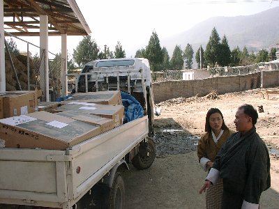
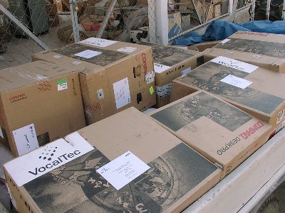
The VocalTec gear arrived from Phuntsholing on the back of a truck. Like most roads it is likely to be fairly dusty, and the computers inside the boxes seen in figure 15 are are not protected by plastic bags or the like. The cause is uncertain but the hard drives in one of the servers failed a month or two after install. One may have to accept that computer components and especially drives will have a lower Mean Time Between Failure (MTBF) under these conditions.


Fig. 15 The VocalTec shipment came in via Phuntsholing

8 Assembly

8.1 Timers


a)
b)


c)
d)
Fig. 16 Converting the timers

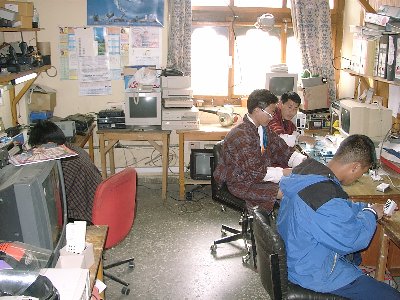
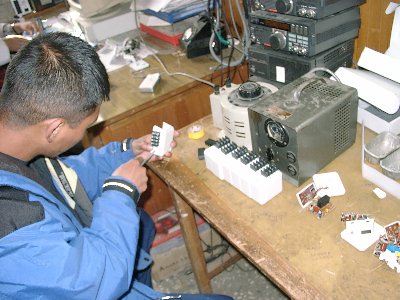
First the timers were converted to 12V. The procedure varies somewhat depending on the timers but one can save some money and  build up capacity for local repair of the repeaters. However the timers were just an interim solution intended only for the pilot project. As described above, a watchdog timer would be the preferred solution. Please see figure 16 above.

8.2 Repeater boxes

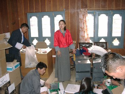
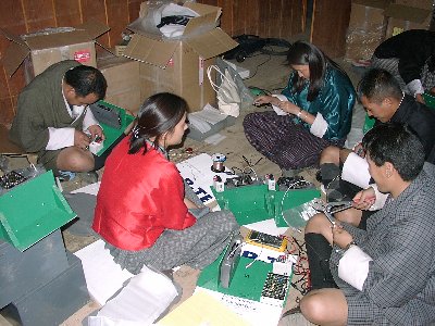
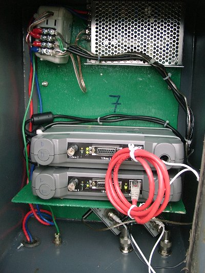
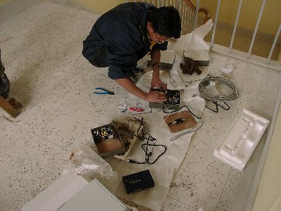
Next the radios were converted to use N connectors instead of the nonstandard R-TNCs that they came with. See the Radio Training Manual [1] for details. Then a mounting shelf was made out of wood and the parts were installed.


a) Directing the workflow
b) Building the repeater boxes
Fig. 17

9 Site preparation

The site surveys were carried out by Bhutan Telecom before the Consultant arrived and were ready for the equipment once the project started. As mentioned before, some of the relevant questions to ask are:

9.1 Installation.

Most installations went smoothly. Sometimes the appropriate fasteners were not available so alternatives were used. Please see Appendix 3 for site pictures.

10 Trouble Shooting

10.1 Network

10.1.1 Problems with routing
Initially the intention was to have two Flytech routers in the NOC connected to different subnets in Limukha and Gelephu. However when the VocalTec servers were set up it didn't seem to be possible to enter anything but a default route in their routing tables because they were Microsoft boxes. Later it was learned that some versions of MS OSs are capable of using full routing tables but there was some doubt expressed that they could do it correctly. So the VocalTec gear was set up to point at the Gelephu box for its default routes, and the Gelephu box pointed to the Limukha box for that subnet. This seemed work fine and attention was focused on making adjustments to the radio network. Also the VocalTec monitoring software was a little too sensitive to dropped packets and variations in timing on the radio network. They eventually had to update their residential gateway firmware and monitoring software to relax their alarm conditions a bit. Because all three of these systems were interdependent and tightly coupled it was very hard to track down problems. In cases like this the best plan of attack is to solve the obvious ones first and then do experiments to isolate the unobvious ones. At one point the Consultant suggested that it would be cleaner to have the packets destined for the Limukha network to go through a separate cable connecting the two routers, rather than having them bounce back out to the switch again. At that time it was thought that there were still radio interference problems that needed to be solved so this wasn't tried. Later the switch configuration was changed to solve a minor problem in the NOC. The Consultant also noticed subtle oddities with the switch under certain conditions but dismissed it as some "feature" that he wasn't aware of. Many people looked at this problem, and several TCP dumps were gone over carefully. The VocalTec engineers noticed some oddities there, but apparently nothing concrete. There were no ICMP redirects or anything else that might indicate a configuration problem. There was the occasional CPE radio that would disappear for a bit and one would see the "No route to host" error. So for the time being work continued on the radio network. Eventually a pattern began to emerge after other changes to the system became less frequent. The calls to the PSTN side from Gelephu always went through but occasionally similar calls from Limukha mysteriously failed. The Consultant then suggested that the default routes be changed to point at the Limukha box and the routing tables in both Flytechs be updated accordingly. There were some other experiments in progress at the time so it couldn't be tried immediately, but when it was, the problem area switched also which indicated that it was a problem at the NOC and not in the radio network.

The Project Manager then suggested that one router should be used instead of two as can be seen in figure 18. This seemed like a good idea, the trade off being there would be (another) single point of failure but that there would also be a spare router. So an E1 card was installed in the Gelephu Flytech which was connected to Limukha and things started working much better. At the time the Consultant returned home there was still a problem placing long distance calls which was eventually solved by another firmware update to the PSTN gateway.

It should be noted that the trouble shooting of the VocalTec system was hampered somewhat by not being able to make test calls without disturbing customers. Or conversely needing to monitor the system for a day or so to wait for a pattern to develop with the customer generated traffic.


Fig. 18 Final network diagram for the NOC and outward links
10.1.2 Bridging vs. Routing
The Cisco radios use Spanning Tree Protocol (STP) to act as network bridges. This will work even if the SSIDS are different if they have a wired connection to each other. They also will allow one to enter routes and act like routers but the Consultant had difficulty making this feature work. This was one of several occasions where the Cisco product didn't perform as documented, however if used in the most common configurations it worked flawlessly. The lesson learned here seemed to be, let bridges be bridges and routers be routers. Instead of giving each repeater a address in it's own subnet and making that the default gateway for it's CPEs, all repeaters in a site were given IP addresses in one subnet which included an interface on the Linux router. This became their default route. Next, virtual interfaces were added for each default route that the CPEs needed, being in different subnets as they were. Since the Cisco radios would bridge these subnets back to the Linux router, as far as the CPEs were concerned they had a local router for each of their subnets. One small advantage of this was that one could experiment with other radios that behaved as routers instead of bridges without changing the CPEs configurations.

Of course bridging is a nice feature, it allows many sub-sites to appear as one seamless network, and probably would be a good choice for other projects. Having different subnets for each repeater was mostly an arbitrary way of organizing the project as much as anything else. For a nice intro to Routing see [5.3], and Bridging see [5.4].

10.2 Radio

10.2.1 Mutual interference
The microwave towers that some of the repeaters were on had a preexisting service known as Digital Radio Multiple Access Subscriber System (DRMASS), which was also in the 2.4 GHz band. The channel used by  DRMASS was below the ones available to the 802.11b radios, but close enough that mutual interference was an issue. These problems manifested themselves differently at each site. At Limukha initially there was noise on the DRMASS voice circuits, and the backbone link would go down periodically. In Gelephu DRMASS didn't seem to be affected but one of the three 802.11b radios was slightly less sensitive. This usually was the radio on the channel nearest the DRMASS frequency.

Various steps were taken to correct the problem at Limukha. First the backbone dishes were changed from vertically polarized to horizontally polarized and different channels were tried. At one point intermod was suspected at one site because the only frequency that would work was the center one available to the 802.11b radios. Note that 802.11b is a compromise between a narrow band signal and full spread spectrum, also known as wide band. The DRMASS channels are even narrower. This indicates that intermod might be possible between them. It was inconvenient and difficult to make trips to the repeater sites but eventually the test for intermod was made and this proved not to be the case. Another related common problem is that the amplifier distorts the signal when over driven, and the distortion can interfere with adjacent channels. Another common problem that can affect closely spaced antennas is side lobe radiation. The radiation pattern does not steadily drop off at the the edge of the usable area, but has smaller lobes at the edges. If antennas are spaced too close together, or are transmitting at a relatively high power then it's possible for the side lobes from one to radiate into another and  desensitize it to it's intended signal. For these reasons it's much better to run one's equipment at the lowest power setting that still allows for some rain fade.

A large portion of the interference to the 802.11b radios at the Limukha hill top were caused by the other 802.11b radio. The Consultant had recommended moving the backbone dish halfway down the tower to help correct this mutual interference and to protect it more from lightning strikes. Eventually it was possible to make another trip to Limukha to do so. At the same time it was also desirable to move the omni antenna to get it a little farther away from the lightning rod though it was in relatively the same placement as the repeaters which were mounted on telephone poles. This proved difficult because it had to be near the top of the tower to hit all the CPEs and the Talo repeater, and the other possibilities put it very close to the DRMASS antennas which caused them unacceptable levels of interference. So the 802.11b omni had to be left where it was. The Talo repeater which provided service to some CPEs that couldn't see Limukha directly seemed to be having problems making itself heard. This was probably because the Limukha omni was in a somewhat noisy environment. So next  the omni was moved onto another pole mounted a short distance away from the tower but it didn't seem to help much, and it might have even increased the interference between the 802.11b radios. Then Talo was upgraded to two radios with one using a dish antenna to talk back to Limukha. This did seem to help. Because the Talo link has since become intermittent the Consultant recommends moving the omni back onto the tower. Additionally it might be possible to lower the  DRMASS antennas a bit to lessen the side lobe interference between them and the omni.

In Gelephu the DRMASS seemed to cause relatively minor interference. The Consultant did some signal measurements for the omni by walking a path around the tower about two city blocks square. When the omni was assigned the lowest channel the noise level was higher at most points along the path. Another oddity which may have had nothing to do with DRMASS was that once or twice a day one of the outlying repeaters would switch parents from a dish to the omni. Sometimes this would happen at four in the morning when the timer turned off the radio for one minute which is understandable. If it turns out that this area can be covered adequately by the omni antenna then it would probably help to have less radios on the tower.

When dealing with neighboring radio services it helps to have extra non-overlapping channels to give each some elbow room. 802.11b is part of the ISM band and different countries have chosen to allocate it different numbers of channels within this band. The Radios used in this project were from the US and only have eleven channels available to them out of a total of fourteen [20.1]. If it were possible to get radios with all fourteen enabled then perhaps coexisting with DRMASS or other 2.4GHz systems would be easier. Here is a tutorial about different strategies for channel allocation [17].
10.2.2 Radio System monitoring
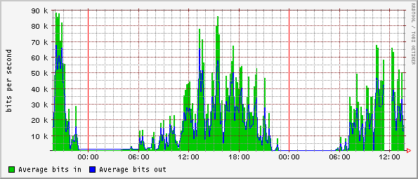
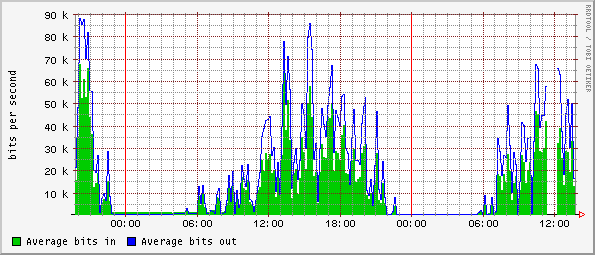
Because the Cisco Bridges were monitorable by SNMP the Cricket router monitoring and graphing package was used to monitor them [5.8]. The Bridges provided two useful types of data, Throughput, and RF link data. For example, in figure 19 one can see graphs for the bandwidth used on the  "backbone" link over a twentyfour hour period. First one notices that the throughput is asymmetrical. This could be caused by one person doing most of the talking on some of the calls. Second that the outgoing in "a" (blue) matches the incoming (green) in "b" which is as it should be. Also if one knows the data rate for the default Codec then the number of simultaneous calls at a given time can be estimated.


a) Throughput for the Dochula dish

b) Throughput for the Limukha dish
Fig. 19 Backbone throughput graphs

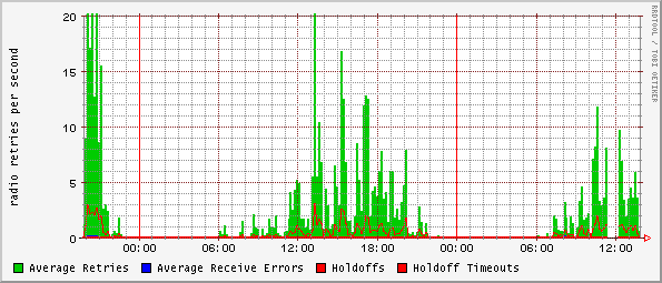
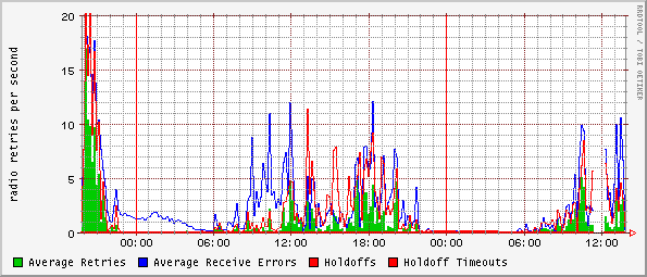
As the bandwidth usage increases so do the RF errors. As mentioned earlier this is somewhat pronounced because the link is simplex. There would still be a small increase in the error rate on a full duplex link but it would be proportional to the throughput in one direction only and not dependent on how much data was being sent back. In figure 20 a one can see that the retires roughly match the receive errors in 20 b. This is typical for a point to point link. Also the red graph in 20 b (Holdoffs)  indicates that the Limukha dish is in a bit of a noisy environment. Holdoff Timeouts are where the radio has waited an unreasonable amount of time for a clear space to transmit a packet. They are also graphed in red but would fill in the area under the graph like the green retires graph. Since this was never seen it means there were no Holdoff Timeouts. This shows that the interference from DRMASS was not severe.


a) Dochula Dish RF errors

b) Limukha Dish RF errors

c) Limukha Omni RF errors
Fig. 20 Sample RF error rate graphs

Figure 20 c shows similar errors for the Limukha omni. It is noticeably different from the other two probably because it is talking on a different frequency and to several CPEs and a repeater. This hints at the limitation of this type of monitoring when several factors are aggregated into one graph. It would be much more helpful to monitor each CPE and look at their error rates because they tend to link back to only one repeater, and as seen in figure 19 each end of a link has virtually a mirror image of the other's information. Unfortunately the Avaya ECs were not SNMP capable. However the Soekris SBC are, and it will be interesting to see how much this information helps in trouble shooting.

Another complementary type of monitoring is to watch the services provided by the system and alert if any fail. Some examples of packages that do this type of monitoring are Big Brother, Big Sister, Netsaint, and Nagios [5.10] - [5.13].

11 VoIP equipment installation and configuration

Most of this was done while the Consultant was finishing up work in Gelephu. Please see the Project Manager's report for details in this area.

12 R&D

At the request of the Consultant an e-tel GW210, two Symbol NetVision phones and, a four port GW built from an old computer were purchased and demonstrated to work with a free Linux based H323 software. Even though this very low cost system performed fundamentally the same functions as the Commercial vendors system it was obviously not ready to be deployed in the field without further development. The Consultant feels that in six months to a year  such a system could give commercial vendors like VocalTec a run for their money. A lot of this software can be found on the Open H323 site [5.5].


Fig. 21 R&D Results Demonstration

The Consultant also brought a Single Board Computer (SBC) and some wireless cards to experiment with. After quite a lot of development He was able to demonstrate a diskless wireless router with these main features.
There were also other features which could have been selected like fire walling.

Because the Thinlaygang school area was one of the sites with two VocalTec GWs which could not be supported by the ECs, and it was a high profile site with a brand new school, the Consultant proposed that the SBC be installed there in the hope that eventually Internet access could also be provided to the school and community. The installation happened very near the end of the Consultants stay but went fairly well. The system worked for a couple of weeks and then developed a problem, which was sad but the simplest thing to do since the Consultant had left was to put back the EC. It would be worthwhile to take more time to burn in a unit and it's firmware for a while before making another attempt.

13 Training

Two trainings were conducted in June, one for the radio equipment and the other for the Flytech routers.

13.1 Radio

In attendance at the radio training were:
  1. Sonam Phuntsho
  2. Sonam Dorji
  3. Sonam Tobjay
  4. Damchu Wangchuk
  5. Samten
  6. Dechen Zam
  7. Tandin Dorji
  8. Pema Chogyel (DIT)
  9. Darma Dhendup (DIT)
  10. Takeshi Sasahara (DIT)
The material covered was from the Radio Training Manual [1], with a question and answer session.
There were several requests for additional training. Mostly from the Technicians who will be responsible for maintaining the network. The Consultant made himself available for other hands on training sessions but everyone was busy finishing up the project so unfortunately  that never happened.

13.2 Flytech

The attendees of the Flytech training were:
  1. Sonam Phuntsho
  2. Sonam Dorji
  3. Tandin Dorji
  4. Ganga Sharma
  5. Tensin Tobgyl
There were two sessions, one covering the basics from the Flytech Training Manual [2]. The advanced session covered routing concepts but frankly there was not enough time to do it justice. More training will be needed in this area.

13.3 Additional training

More experience with setting up different configurations of radios, and trouble shooting is needed. This would involve learning about the different menus/tools available to test and monitor the network.

The Technicians need a deeper understanding of IP addressing, and how to put subnets together and add static routes for them. Because the Cisco radios do bridging well but apparently do less well at routing, the network is an 'interesting' combination of bridging and routing. If the network configuration becomes broken during an upgrade then they would most likely be the ones to drive to the remote sites and fix it using a laptop and serial cable. They would be more prepared to handle these tasks if they had a better understanding of networking.

Last but not least they need more experience with the Unix command line environment. There are several reasons for this. Windows has been found to not always be a reliable platform to trouble shoot from so the laptops tend to be set up to also boot Linux. Most of the useful tools that are used for trouble shooting are Unix/Linux based for similar reasons. Several of the routers in use are Unix/Linux based and to set them up properly one needs to know the local editor and command line syntax. Also the knowledge in this area would come in handy when coordinating work with Druknet (if that's needed) since Druknet has several Unix based servers. Other routers like Cisco's have environments that were derived from Unix systems so that knowledge should transfer easily to these platforms as well.

14 Recommendations

14.1 Radio

14.1.1 Backbone
To adequately provide enough capacity for VoIP and higher bandwidth services higher speed backbones need to be researched and tested in the field. A cost tradeoff study should be conducted comparing half and full duplex equipment in the speed ranges of 50. 100. and 150 Mbps.
14.1.2 Repeaters and CPEs
The cost of the repeaters could probably be reduced as well as their power consumption. This would especially help the solar sites be more cost effective. More R&D needs to be done on repeaters and CPEs using low cost SBCs. One immediate cost reduction for the CPEs is to use the Poynting Yagi antenna [5.2] which is about a quarter of the cost of the Hyperlink. It would be nice to find a smaller commercial power battery charger as well.

For the solar CPEs try out the BZ products MPPT charge controller[13.1].

Move the Limukha omni back to the top of the tower.

Remove one of the Dish repeaters on the Gelephu tower and set the remaining repeaters to non-overlapping channels that are at the top end of the range. This will minimize the interference between the 802.11b radios and DRMASS.
14.1.3 Monitoring
New CPE equipment should be designed which is SNMP capable so that RF link status can be easily monitored so problems can be more quickly isolated.

Complementary monitoring packages should be installed to keep tabs on the state of the network, such as NetSaint [5.12], or Big Sister [5.11].
14.2 VoIP
VocalTec has worked hard to make their equipment reliable in the wireless environment and it seems to perform at the level one would expect in a commercial setting. However there are areas in Bhutan and other developing nations where the high cost of such a system would not be viable. Perhaps a VoIP system based on free software is worth looking into. For example the Sherubtse college area in Eastern Bhutan might benefit from such a system. Some other projects in this vein are the Jhai Remote IT Village Project [44].

14.3 Billing

Since there is already a lot of software development being done in Bhutan for the government, perhaps an in country billing system could be developed using Druknet's as a model.

14.4 Software

14.4.1 General guidelines
When choosing software or hardware/firmware packages for a system keep in mind these general guidelines. This all adds up to low TCO.
14.4.2 Specific features that are important in a wireless system
14.4.3 Specific features that are important in a VoIP system

14.5 Internet access test sites

Thinlaygang Middle Secondary School should be set up with Internet access using the next revision of the Soekris SBC. Other schools and communities should be selected for ICT center pilot studies so that students and the public can benefit from new technologies.
14.5.1 Solar powered sites
A lot of schools and communities don't have power and won't be getting it in the foreseeable future. Solutions need to be found for these situations as well. Very low power computers can be used and run from small solar installations. Probably the current solar CPE sites could support part time laptop use without adding panels. An inexpensive laptop should be setup at Limukha school to explore this possibility. As in the Jhai project [44], the hard drive should probably be replaced with a compact flash card. Of course appropriate security measures should be taken.

14.6 Lightning protection

Since lightning is extracting its toll on the Gelephu CPEs the use of TransZorbs or the ONEAC OnLine products should be explored there.
On some high profile sites with lightning rods perhaps try out the Cortana Stati kitty [25].

Consider using a irreversible compression-type bonding system for grounding.

14.7 Mounting

Explore the technique of using an epoxy holding compound as a better alternative to expansion bolts. This would allow the use of simple all-thread cut to length on site, and also usable as u-bolts.

14.8 Local construction

It seems to help technology transfer and skill building to look for practical things to construct in house. The timer conversion and weather tight box are two good examples. Perhaps the LVD circuit [A.1] would also make a good local project.

14.9 Transport

It seems that a couple of improvements to how things are transported would help. The Consultant noticed that items would occasionally fall off the truck as it rumbled down the road. Even though an effort was made to tie the load securely there were often lots of small parcels that could slip out. A cargo net would help a lot here, and they are quick and easy to tie down. If cargo nets were not readily available then it would make a great cottage industry. They would be very easy to make at home using a simple board with pegs as a jig.

Sometimes telephone poles and GI pipes need to be transported and they are also a little difficult to tie down on the back of a truck. A roof rack with a support near the tail gate would be very handy for tying these down. These could also be made in Bhutan in a simple welding shop.

14.10 Further research

Some further research should be done using Open H323 and related software to build a viable low cost VoIP system.
Also more systems should be developed using SBCs and high power PCMCIA cards. This would eventually yield a lower cost more robust system.

15 Conclusion

This project was successfully deployed and commissioned, and should be tested further by providing Internet access to some schools and communities. Much has been learned and a new generation of equipment is already in the design stages which will correct most of the known shortcomings of the current generation. Most notably the issues being addressed are scalability, configuration management, better monitoring capabilities, lower power consumption,  and high speed backbones. This will all add up to a lower Total Cost of Ownership or TCO. Below are some remarks by the Consultant's local counterpart(s) summarizing the system's evaluation.

15.1 Concluding remarks by local counterpart

  1. The suitability of the technology for the provision of rural access?

  2. Can the equipment meet the requirements of BT as well as the DIT?

  3. Reliability of the equipment available?

  4. Power consumption and reliability of the power supplies as Solar power supplies will have to be employed at most sites?

  5. System flexibility and capacities?

  6. Installation and testing methods. Ease of installation and testing?

  7. Reaction of people using this system as compared to using the traditional systems?


A Annexes

A.1 LVD Circuits

The Consultant was dissatisfied with the quality of LVD devices locally available to some developing nations and felt the the high quality ones were too costly. After some research a couple of articles were found with schematics of LVDs. These seemed to be too complex, or at least more so than they really needed to be.


Fig. A.1.1
Here is one that originally was half of a solar charger


Home power magazine published two articles with LVD schematics, one was also a solar charger and can be found at: http://www.solorb.com/elect/solarcirc/ccntlvd/ The other which seems to be just the LVD part without the solar charger is here: http://www.homepower.com/files/lvdhp60.pdf.


Fig. A.1.2
Burton Lang's, (VE2BMQ) LVD Circuit


Burt Lang thought that another circuit published in QST Nov '93 was also too complicated. So he came up with this basic design seen in figure A.1.2. He has an excellent page with lots of information including many optional features here:http://www.cam.org/~burt/circuits/lvdisc.html


Fig. A.1.3 The Consultants LVD Circuit

The page describing this circuit can be found here: http://www.bhutan-notes.com/clif/LVD_circuit.html. To be fair the hysteresis is fixed so adjusting the off point changes the on point but one could use a variable resistor instead of the 10M ohm one if that was important. It's also worth considering that one probably wants all devices set to the same standard and not readjusted in the field. This is why commercial LVDs are often preset at the factory and not user adjustable.

A.2 Battery charging and desulfation

 There are some new techniques for charging batteries that can extend their life many times what was expected. Here is an excerpt from an article by the National Renewable Energy Laboratory.


[16]NREL Research Teams Win Three R&D 100 Awards

[...]
The current interrupt charging algorithm is a simple approach for recharging lead-acid batteries that extends the cycle life of the batteries by 300 to 400 percent. Lead-acid batteries used in electric vehicles have, until now, lasted only about 150 to 200 deep discharge cycles, primarily because the batteries have been charged using a constant current and voltage.

In contrast, NREL and its partners, Recombination Technologies and Optima Batteries, devised a new and more efficient way to charge batteries. Their method involves applying a current to the battery for five seconds to overcharge the battery slightly, then interrupting the current for five seconds. This allows the battery to cool and avoid going into the oxygen recombination cycle, which leads to early failure of the negative battery plate due to oxidation of sulfuric acid into sulfate.

"Our idea was to increase the cycle life of lead acid batteries to have less waste in our landfills," said Mechanical Design Engineer Matt Keyser. "By increasing the cycle life, consumers will use fewer batteries over time."

Visit NREL online at www.nrel.gov.
[...]
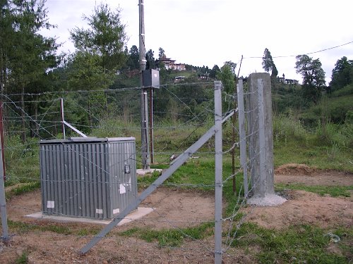
Here is a more detailed article on these new charging algorithms [7.1].
Sulfation is what happens to a lead acid battery if it is not fully charged, and equalized every few weeks or so. Many batteries have their lifetimes severely shortened by sulfation. Here is a Circuit for reversing the process: [8].

A.3 Pictures

A3.1 Talo Repeater site
Talo was our first standalone repeater site, and is located in the Limukha area. The land was donated by a kind hearted farmer.


a) Talo repeater site
b) Commercial power housing
Fig. A.3.1.1


a) Antenna
b) Box
Fig. A.3.1.2
A.3.2 Ai Bridge site
Ai Bridge is another site with Commercial power in the Gelephu area.


a) Repeater shack
b) Commercial power battery charger and battery
Fig. A.3.2.1


a) Inside shack
b) Inside box
Fig. A.3.2.2
A.3.3 Chusegang repeater site
Chusegang is an example of a solar powered repeater site. It is near Gelephu in the hot and humid low lands of Bhutan.


a) Chusegang site showing earthing pits
b) Raising the repeater


c) Installing solar and fencing
d) Nearly finished site
Fig. A.3.3.1

Four earthing pits were dug, which  copper plates were then placed in with a loop of wire connecting them that also ran to the lightning rod. The pits were filled with alternating layers of salt and charcoal. Concrete footings were pored for the repeater pole and fence posts. The grounding for the solar sites were very simple. The solar and repeater equipment grounds were connected to the lightning rod wire at ground level.


a) Antenna
b) Repeater box
Fig. A.3.3.2


a) 360 Ah battery bank
b) Trace C40 Charger and LVD
 
c) Box
Fig. A.3.3.3


The Solar equipment was housed in a nice weather proof box recycled from another project. The Amara Raja Power Stack battery bank had to be taken apart and reassembled without its supporting frame for it to fit. The front cells hung over the edge of the metal platform a bit, later that was fixed with a block of wood. There should probably be a fuse between the batteries and the charger, oops!
A.3.4 Umling CPE


a) Dwelling and forestry office with CPE
b) Nearby Basic Health Unit (BHU)


c) Back side with Antenna and coax
d) Closeup of Antenna
Fig. A.3.4.1


a) Fastening equipment to plaster walls is difficult
b) Completed CPE
Fig. A.3.4.2


Fig. A.3.4.3 Some of the families served in this community are quite large!
A.3.5 Limukha backbone and repeater site
Originally the backbone dish was mounted at the top of the tower with the omni as seen in figure A.3.5.1 b.


a) Limukha tower
b) The dish was originally mounted at the top
Fig. A.3.5.1

Later it was moved to the center of the tower as shown in figure A3.5.2 to solve some interference problems between it and the omni and also the DRMASS system.


Fig. A3.5.2 Then the dish was moved down to provide more separation between it and the omni.


a) Dish visible in center of tower
b) Repeater box showing two bridges with crossover cable
Fig. A.3.5.3

Figure A.3.5.3 a shows the 802.11b dish in the center of the tower dwarfed by the giant microwave dishes. Figure b shows the inside of the repeater box with the red crossover cable connecting the two Cisco bridges. The top one links back to Dochula and the bottom one provides service via the omni to the Limukha area.
A.3.6 Limukha School
Limukha School is just a short drive from the Repeater tower, almost at the same elevation. The windy mountain road that descends to the valley below is impassable by vehicle for months at a time during the monsoon season. Good communications is a welcome improvement for this community.


Fig. A.3.6.1


a) Corner of School building
b) Roof line


c) Solar panels
d) From below
Fig. A.3.6.2


a) CPE under roof
b) Antenna mast fastening
Fig. A.3.6.3
A.3.7 Thinlaygang school
Thinlaygang school was not even quite finished when the team arrived to install the VoIP equipment. Initially the power was off more than it was on and there were some problems keeping the batteries charged but it all came together soon enough.


a) Thinlaygang school
b) A brand new classroom
Fig. A.3.7.1

There wasn't an easy way to get up too the roof, and even though it was still a construction site there were no ladders available so one had to be made out of bamboo poles (figure A.3.7.2)


a) Building the ladder out of bamboo poles
b) The ladder in place and braced
Fig. A.3.7.2

The first version of the CPE at this site had a hub for the two VocalTec gateways so the power supply had to be augmented with a additional power cable.


a) Building the power supply, and EC box
b) Lunch time!
Fig. A.3.7.3
The antenna was fairly typical, notice the block of wood to allow adjustment of the inclination in figure A.3.7.4 b.


a) Antenna pointing back to Talo repeater
b) Closeup
Fig. A.3.7.4


The First CPE in figure A.3.7.5 a had two GWs which as mentioned before didn't work with the Avaya EC. Unfortunately the GWs in Gelephu took a lot of hits from lightning so the second one was redeployed elsewhere while new ones were ordered. The second version of the Thinlaygang CPE used the Soekris SBC shown in figure A.3.7.5 b. Unfortunately the SBC developed a problem after the Consultant left so it had to be retired early. Perhaps another try can be made after more R&D is done.


a) first CPE setup
b) CPE with Soekris SBC
Fig. A.3.7.5

A lot of children in Thinlaygang have never even seen a telephone before so to have them at the school and in town was quite a change for everyone. Hopes are high that Internet access will be coming soon.


a) One of many classes hoping for Internet access
b) The Principle with his hub and network cable
Fig. A.3.7.6


A.4 List of Figures

1 Limukha Area Diagram
2 Gelephu Area Diagram
3 Original network diagram for the NOC
4 NOC in the Thimphu switching room
5 Problems with expansion bolts
6 Proper taping of connections
7 The commercial charger was a bit larger than it needed to be
8 Inside the commercial charger
9 Weather tight box
10 Different grounding examples
11 Equipment grounding examples
12 Solar Panel at Limukha with static dissipating points
13 Example shipments
14 Examples of minor rough handling by DHL
15 The VocalTec shipment came in via Phuntsholing
16 Converting the timers
17 Building the repeater boxes
18 Final network diagram for the NOC
19 Backbone throughput graphs
20 Sample RF error rate graphs
21 R&D Results Demonstration
A.1.1 Half of a solar charger
A.1.2 Burton Lang's, (VE2BMQ) LVD Circuit
A.1.3 The Consultants LVD Circuit

A.5 List of Tables

1 A quick comparison of existing and proposed 802 wireless standards
2 Calculations for solar system size

A.6 List of Acronyms

AP
Access Point
BHU
Basic Health Unit
BT
Bhutan Telecom
CDR
Call Data Record
CF
Compact Flash
CIR
Committed Information Rate
CPE
Customer Premise Equipment
CSN
Circuit Switched Network
dBi
Decibels relative to an Isotropic radiator
DIT
Department of Information Technology (in Bhutan)
DRMASS
Digital Radio Multiple Access Subscriber System
EIRP
Equivalent Isotropically Radiated Power
FCC
Federal Communications Commission (in the US)
GK
Gate Keeper
GW
Gateway
ITSP
Internet Telephony Service Provider
LAN
Local Area Network
LCR
Least Cost Routing
LOS
Line Of Sight
LVD
Low Voltage Disconnect
MAN
Metropolitan Area Network
MOV
Metal Oxide Varistor
MPPT
Maximum Power Point Tracker
MTBF
Mean Time Between Failure
NIC
Network Interface Card
NLOS
Near Line Of Sight
NOC
Network Operations Center
PCI
Peripheral Component Interconnect
PCMCIA
Personal Computer Memory Card International Association
PoE
Power over Ethernet
POTS
Plain Old Telephone Service
PSN
Packet Switched Network
PSTN
Public Switched Telephone Network
SBC
Single Board Computer
SNMP
Simple Network Management Protocol
SNR
Signal to Noise Ratio
SOC
State Of Charge
STP
Spanning Tree Protocol
TCO
Total Cost of Ownership
TOF
Time Of Flight
UTP
Unshielded Twisted Pair (Cat 5)
VRLA
Valve Regulated Lead Acid (battery)
WAN
Wide Area Network
WLL
Wireless Local Loop


R References

R.1 General

[1] Radio Training Manual http://www.bhutan-notes.com/clif/Radio_training.html
[2] Flytech Training Manual http://www.bhutan-notes.com/clif/Flytech_training.html
[2.1] Bhutan: Wireless IP based Rural Access Pilot Project, By Tensin Tobgyl http://www.itu.int/osg/spu/ni/futuremobile/technology/bhutancase.pdf
[3] VocalTec Communications Ltd. http://www.vocaltec.com/
[4] E-tel Corporation http://www.e-telcorp.com/ and their GW210 wireless gateway.
[5] Symbol Technologies http://www.symbol.com/ Makes the NetVision Phone.
[5.1] Poynting Antennas and Electromagnetics http://www.poynting.co.za/
[5.2] Poynting 12dBi Yagi antenna http://www.poynting.co.za/antennas/ism_24ghzyagi12dbi.shtml
[5.3] Intro to Routing http://www.cisco.com/univercd/cc/td/doc/cisintwk/ito_doc/routing.htm
[5.4] Intro to Bridging http://www.cisco.com/univercd/cc/td/doc/cisintwk/ito_doc/bridging.htm
[5.5] Open H323 site http://www.openh323.org/
[5.6] Epoxy holding compound http://www.williamsform.com/Concrete_Anchors/Chemical_Concrete_Anchors/chemical_concrete_anchors.html
[5.7] ScotchKote linkshttp://products.3m.com/usenglish/electronics_mfg/electronics_esm.jhtml?powurl=QQLFZL8Q7NbeDPB1Q1MJ7NgeGST1T4S9TCgvWK8GCR2GN3gl
http://www.paigewire.com/Specs/3Mscotchkote.html
[5.8] Cricket Home Page http://cricket.sourceforge.net/
[5.9] Mon system monitoring package http://www.kernel.org/software/mon/
[5.10] Big Brother http://www.bb4.org/
[5.11] Big Sister http://bigsister.graeff.com/
[5.12] NetSaint http://netsaint.sourceforge.net/
[5.13] Nagios http://www.nagios.org/

R.2 Batteries

[6] A short history of batteries http://www.hepi.com/basics/history.htm
[7] Sealed Lead Acid Battery Charging Basics http://www.acpropulsion.com/PDF%20files/PbA%20for%20EVs.pdf
[7.1] Charging Algorithms for Increasing Lead Acid Battery Cycle Live for Electric Vehicles http://www.ctts.nrel.gov/BTM/pdfs/EVS17pres.pdf
[8] Lead Acid Battery Desulfation Pulse Generator http://shaka.com/~kalepa/desulf.htm
[9] The Truth about Opportunity Charging http://www.cdtechno.com/cd/library/papers/opcharge.htm
[10] Sandia National Laboratories Battery Reports http://www.sandia.gov/pv/bos/batteries.htm
[11] A study of Lead-Acid Battery Efficiency Near Top-of-Charge and the impact on PV System Design http://www.sandia.gov/pv/bos/batpapsteve.pdf
[12]Vanadium Fuel Cells made in Thailand  http://www.vanadiumbattery.com/

R.3 Solar

[13] Notes on peak power tracking http://www.ka9q.net/pv/pptnotes.html
[13.1] Maximum power point tracking charge controller http://kingsolar.com/catalog/mfg/bzproducts/mppt200.html
[14] A short list of solar charge controllers with LVDs
Trace C12 http://www.traceengineering.com/products/charge_controller/index.html
SCI 30 AMP REGULATOR (SC1/30) http://www.solarexpert.com/Chargecontrol/SCI.html
PS30 http://www.e-marine-inc.com/products/charge_controllers/photostar.html
Lyncom N35 35 amp solar charge controller with LVD http://www.solar-electric.com/lynn3535amps.html
Prostar 30 http://www.solarpowerstore.com/canada/controllers.htm
Steca 30 Omega http://www.cetsolar.com/steca.htm
[15] A short list of standalone LVDs
Model 8000124, $145, http://www.buytruckstuff.com/product.asp?selcategory=17&p_gpID=49
Model LVD 12-30, $133, http://www.marconi.com/media/6-11.pdf
PR/SS-LVD8/16-12AD, $63.05, http://www.solardepot.com/photovoltaic_pvcatalog/solar_electricity_catlvd.html
Cir-Kits SPC2 six amp solar charge controller with LVD kit, $55,  http://www.cirkits.com/solar/spc2.html
LVD10 and LVD20 http://www.xenotronix.com/products/lvdc.htm
Intra LVD http://www.intra-tech.com/products/prodlow.html
Surepower LVD 130512 http://www.surepower.com/pdfs/lvd.pdf

R.4 Wireless

[17] Tutorial on 802.11b spectrum usage http://www.euro.dell.com/countries/eu/enu/gen/topics/vectors_2001-wireless_deployment.htm
[18] IEEE Call for Interest Session  March 12, 2002 http://grouper.ieee.org/groups/802/16/docs/02/80216-02_17.pdf
[19] Frequency Domain Equalization for 2-11 GHz Broadband Wireless Systems http://www.ieee802.org/16/tutorial/80216t-01_01.pdf
[20] 2 Tinkerers Say They've Found a Cheap Way to Broadband, By JOHN MARKOFF, June 10, 2002
This article can probably be found at one of these URLs:
http://www.bostonwireless.org/mail/msg00064.html
http://www.ieee802.org/secmail/msg02424.html
http://www.nytimes.com/auth/login?URI=http://www.nytimes.com/2002/06/10/technology/10WIRE.html&OQ=exQ3D1025054574Q26eiQ3D1Q26enQ3Df9c7eb2d241cc542
[20.1] Assigning 802.11b Access Point Channels http://www.80211-planet.com/tutorials/article/0,,10724_972261,00.html
[20.2] Regulations Affecting 802.11 Deployment http://www.lns.com/papers/part15/Regulations_Affecting_802_11.pdf
[20.3] Avaya Ethernet Converter http://www.hyperlinktech.com/web/avaya/avaya_converter.php
[20.4] Linksys client adapter http://www.linksys.com/products/product.asp?grid=22&prid=432
[20.5] Introduction to 802.11b http://www.mobilecomms-technology.com/projects/ieee802/
[20.6] Hyperlink Technologies http://www.hyperlinktech.com/
[20.7] YDI http://www.ydi.com/
[20.8] Cisco 350 Series 802.11b Radios http://www.cisco.com/en/US/products/hw/wireless/ps458/index.html
[20.9] Orinoco/Wavelan http://www.orinocowireless.com/

R.5 Lightning protection

[21] Review of Dynamic Changes in USA Lightning Codes and Standards http://www.lightningsafety.com/nlsi_bus/CodeReview2002.html
[22] K1TTT Technical Reference http://www.k1ttt.net/technote/techref.html
[23] K1TTT on grounding and lightning protection http://www.k1ttt.net/technote/onepoint.html
[24] K1TTT on Spiny balls vs rods and some other notes on lightning grounds http://www.k1ttt.net/technote/ground.html#balls
[25] Cortana Stati-Cat http://www.mwpersons.com/Cortana.html
[26] Substation Grounding Connectors IEEE STD 837-1989 Test Series http://www.petir.com/mainfr.asp?linkurl=http://www.erico.com/erico_public/pdf/fep/ShortIEEE837.pdf
[27] THE EARTHING PRACTICE AND ITS EFFECTS ON A FIELD STATION PERFORMANCE http://www.prl.res.in/~bobra/EARTH/html1/index1.html
In particular chapter one http://www.prl.res.in/~bobra/EARTH/html1/chapt1.htm
[28] Introduction Of AD Series Anti-erosion And Friction-reducing Polymer Product http://www.cdyinqiao.com/doce/2.htm
[29] Exothermic Welding Material http://www.exothermicweld.com/
[30] Erico CADWELD® product http://www.cadweld.com/erico_public/brand/CadweldGround.asp
[31] TransZorbs http://www.transzorb.com/
[32] ONEAC http://www.oneac.com
[33] ONEAC POTS Line Protection http://www.oneac.com/voicedata.html

[33.1] Irreversible compression connectors http://www.burndy.com
[33.2]Subpage of commpression fittings http://12.30.8.43/fci/categories.asp?TreeID=COMPRESSION_GROUNDING
[33.3]Look at the section titled HYGROUND Irreversible compression system in this document http://www.fciconnect.com/pdffiles/brochures/2001_Telecom_pgs_118-183%20.pdf
[33.4] The Scope of UL 467 http://ulstandardsinfonet.ul.com/scopes/0467.html

R.6 Timers

[34] Intermatic DT17C 7-Day Heavy-Duty Grounded Programmable Digital Timer http://www.intermatic.com/consumer/dt11c.htm http://www.amazon.com/exec/obidos/tg/detail/-/B00004W4WU/qid=1032076194/sr=8-2/ref=sr_8_2/002-7720296-0245635?v=glance&s=office-products
[35] 12V Digital timer Model SG/AE-TS12V http://www.solardepot.com/photovoltaic_pvcatalog/solar_electricity_catlvd.html

R.7 SBCs

PC104 form factor SBCs
[36] MOPS/520 http://www.jumptec.de/product/data/pc104/mops520e.html
[37] PC/104-PCMCIA-1http://www.jumptec.de/product/data/pc104/pc_104_pcmcia1_e.html
[38] MZ104-1MB http://www.tri-m.com/products/tri-m_engineering/mz104.html
[39] Another PCMCIA slot card for PC104 SBCs http://www.tri-m.com/products/aaeon/pcm3115b.html
[40] VersaLogic Panther PC104 http://www.versalogic.com/Products/DS.asp?ProductID=51
Nonstandard formfactor SBCs
[41] Musenki M-3 Wireless Access Point http://www.musenki.com/M-3-datasheet.pdf
[42] Soekris Engineering net4521http://www.soekris.com/net4521.htm

[43] List of Embedded Linux distributions http://linux-embedded.com/software.php3

R.8 Other Wireless and VoiP Projects

[44] Jhai Remote IT Village Project http://www.jhai.org/jhai_remoteIT.html
[45] Wireless Networks: A Cost-Effective Way to the Internet http://www.comms.uab.es/inet99/inet98/6x/6x_1.htm
[46] Wireless Data Transmission in the Andes: Networking Merida State http://www.comms.uab.es/inet99/4d/4d_1.htm
[47] Applications of High-Speed Wireless Solutions for Developing Countries: Lessons Learned in Latvia and Moldova http://www.comms.uab.es/inet99/4d/4d_2.htm
[48] WIRELESS INTERNET ACCESS in Latvia http://lucilia.ebc.ee/%7Eenok/radiolink/HTMLDocument.html
[49] High-Speed Internet Access via Stratospheric HALO Aircraft http://www.comms.uab.es/inet99/4d/4d_3.htm
[50] The original project proposal http://www.bhutan-notes.com/clif/bt_rural_access_pilot.html